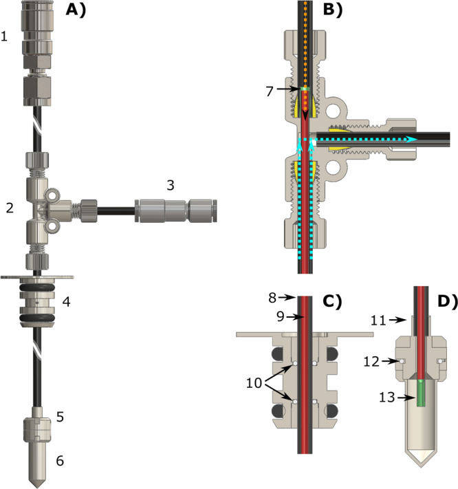
Fig. 1. Custom fluid path (CFP) illustration.

Technical drawings of the CFP (A) and zoomed section of the T-valve indicating inner (orange arrow) and outer (cyan arrows) flow directions (B), dynamic sealing (C), and sample threaded vial (D). Numbers indicate the most important components of the device: quick release connection (1), T-valve (2), one-way valve (3), dynamic sealing (4), vial top part (5), vial bottom part (6), outer-lumen to inner-lumen transition (7), black PEEK outer-lumen (8), red PEEK inner-lumen (9), dynamic sealing silicon O-ring (10), laser-welded joint (11), vial PTFE O-ring (12), nozzle (13).
