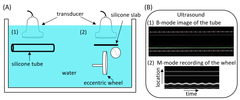
Figure 1.
Study set-up for ultrasound system bias estimation (A) and how it appeared in the ultrasound measurements (B). Two-part phantom set-up consisting of a silicone tube (1), used to assess inter- and intra-scanner biases in diameter and wall thickness, and an eccentric wheel with a silicone slab mounted on top of it (2), used to assess the bias in distension. (B.1): Example of a B-mode image for the silicone tube. The white dot markers indicate the outer tube–water echo interfaces (appearing as horizontal white lines) of the near (top) and far (bottom) walls of the silicone tube used to measure the diameter. The green line indicates the inner tube–water echo interface of the far wall, which, together with the far wall outer echo interface, was used to measure wall thickness. (B.2): Example of an M-mode acquisition of the wheel ‘distension’. The white sinusoidal line reflects the motion of the wheel surface, while the two less echogenic parallel reflections above the undulating line indicate the silicone slab.

