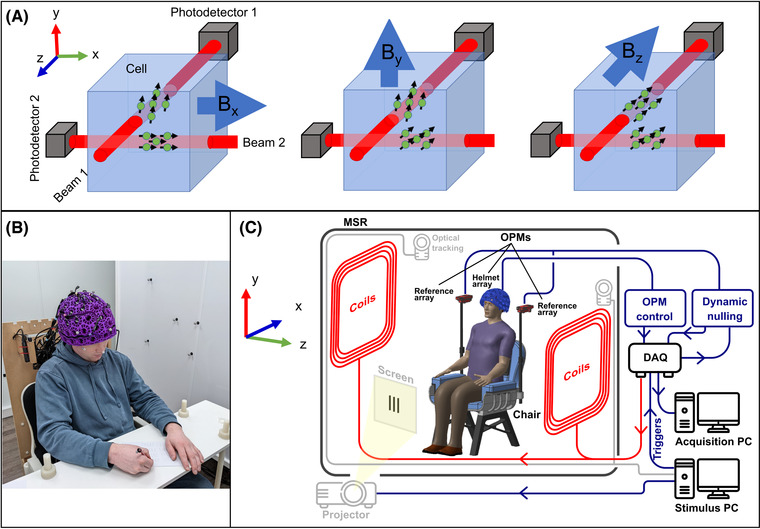
FIGURE 1.

System overview. (A) Schematic diagrams of a triaxial OPM. Two independent laser beams are projected through the vapor cell. The beam oriented in z allows measurements of the field components Bx and By. The beam oriented in x allows measurements of the field components Bz and By. These four measurements can be combined to determine the full vector magnetic field. Note, however, that By is measured twice and thus has marginally lower noise. (B) Photograph of a participant wearing the OPM‐MEG helmet, taking part in the handwriting paradigm. (C) A schematic diagram of the OPM‐MEG system. The participant is placed in a magnetically shielded enclosure (in this case, a room of internal dimension 3 × 2.4 × 3 m3, whose walls comprise four layers of mu‐metal and a single layer of copper). Biplanar coils are placed on either side of the participant for background field control. Data acquisition and storage, as well as coil control, are implemented via digital acquisition systems coupled to a PC. A second PC controls the experimental paradigm and motion tracking.
