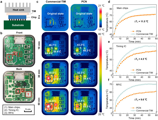
Fig. 5.
Thermal management application of PEG@TPU/BNNS-es (PCN) film in a 5G base station. a Schematic diagram showing a chip integrated with a TIM in a 5G base station. b Optical photographs showing the front side (top) and the back side (bottom) of the 5G base station (without cover), and the regions identified by red squares as regions 1–3, corresponding to the main chips, timing IC and RFIC, respectively. c Infrared thermal images of the 5G base station integrated with commercial and PCN TIMs. Surface temperature versus time in d region 1, e region 2 and f region 3 in the 5G base station integrated with commercial TIM and PCN

