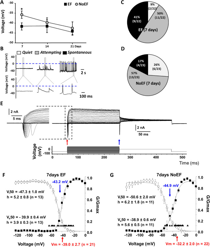
Fig. 2.
Effect of EF on resting membrane potential (Vm) and voltage-gated Na+ current activation and inactivation characteristics of NSCs. A. Summary plot of the resting membrane potential (Vm) ontogeny of EF and NoEF treated NSCs at days 7, 14 and 21. Recording were performed in current-clamp. *P < 0.03. B Exemplar traces of Vm in NSCs with 7-day EF or NoEF treatment, exhibiting no activity—Quiet (white); Attempting activity with spontaneous action potential-like oscillations below 0 mV (gray); Spontaneous activity with genuine spontaneous action potentials (black). C, D Pie charts displaying percentage and proportion of various types of neuronal activity (Quiet, Attempting and Spontaneous) in 7-day EF or NoEF, respectively treated NSCs. E Exemplar family of whole cell currents (upper lane) during the activation/inactivation voltage protocol (lower lane). Inset (right) illustrate Na+ currents. Peak Na+ current activation and inactivation levels were shown by the red and blue arrows, respectively. F, G Mean activation and inactivation characteristics of normalized conductance (G/Gmax) of whole-cell Na+ currents recorded in 7-day EF and NoEF treated hiPSC. The activation curves were depicted by the filled squares. The inactivation curves were shown by the empty circles. The individual Vm values were labeled as the filled upward triangles. The mean Vm values were labeled as the red arrow on abscissa in each panel. Va50: Voltages of half maximal action. Vi50: Half maximal inactivation. The h factors: mean crossing points (downward arrows) number of cells recorded for each group (n)

