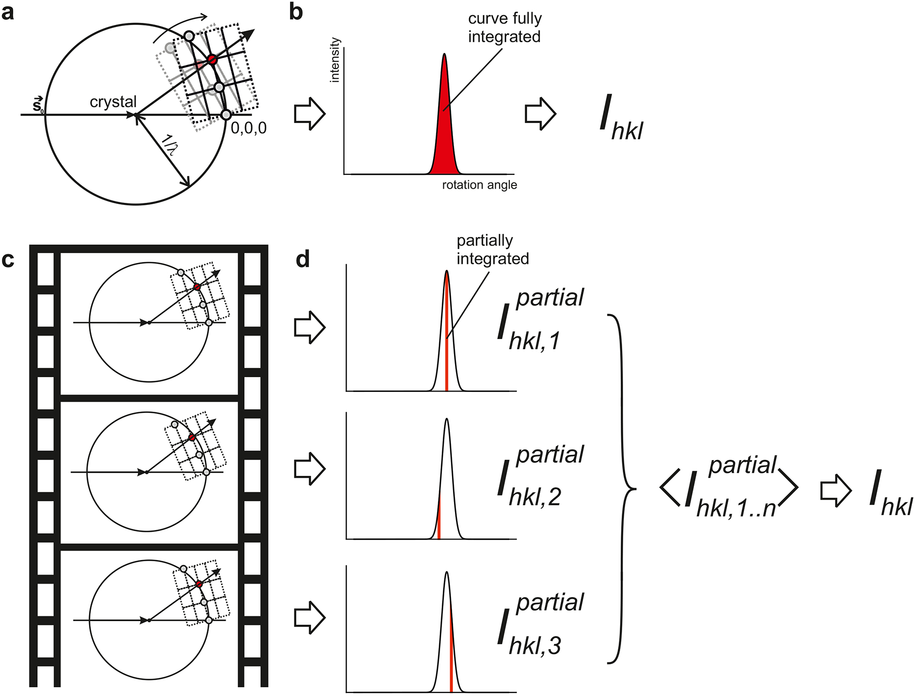
Fig. 4 |. Integration of intensities in rotation- and serial crystallography.

a | The Ewald construction can be used to visualize diffraction geometries. The incoming radiation hits the crystal located at the center of the Ewald sphere, which has radius 1/λ. The reciprocal lattice is drawn, with the origin at the position where the direct beam intersects the Ewald sphere behind the crystal. In conventional rotation crystallography, the crystal is rotated, and the reciprocal lattice rotates (curved arrow), causing reciprocal lattice points (spheres) to move through the Ewald sphere, rotating into and out of reflection condition. b | The observed intensity of diffraction from a certain reciprocal lattice point (such as the red sphere in panel a.) increases, then decreases with rotation angle. Integrating this rocking curve yields the intensity Ihkl. c | In SFX there is no a priori control of the crystal’s orientation, and intersection of the red reciprocal lattice point with the Ewald sphere is a stochastic process. d | The crystals are effectively motionless during the extremely brief exposure. As a result, the observed diffraction corresponds to a thin slice of the rocking curve of each reflection. Partial intensities from many exposures need to be averaged to give Ihkl for each reflection.
