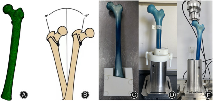
Fig. 2.

The truncated digital femur was processed by meshing (A) for element creation. five different α angles ranging from 10° to −10° (B) were selected for embedding of the 3D femoral model in the FEA and the artificial femur used in the biomechanical experiment. The tooling for osteotomy (C) and embedding (D) of the artificial femur were designed and assembled. The embedded sawbone was assembled on to the biomechanical testing machine (E).
