Fig. 7.
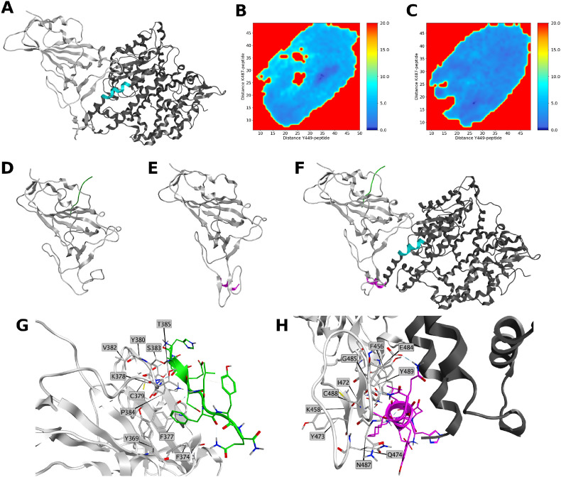
A) 3D structure of SpikeRBD:ACE2 complex (PDB entry: 6M0J). Spike RBD is represented in light grey ribbon, ACE2 is rendered in dark grey ribbon. Sequence of the protein consisting of WT peptide is highlighted in cyan; B–C) PMFs obtained from distances of CA atoms of residues Y449 and K487 to CA atoms of B) 1 and C) 6. PMF is shown in color bar (0.0–20.0 kcal/mol range) from dark blue to red; D) Lowest energy conformation obtained from the simulation of SpikeRBD:1 complex. SpikeRBD is represented in light grey, WT is rendered in green; E) Lowest energy conformation obtained from the simulation of SpikeRBD:6 complex. SpikeRBD is represented in light grey, 6 is rendered in purple; F) Superposition of 1 and 6 to SpikeRBD:ACE2 complex. Spike RBD is represented in light grey ribbon ACE2 is rendered in dark grey ribbon. Sequence of the protein consisting of 1 is highlighted in cyan, 1 is rendered in green, 6 is rendered in purple; G) Site view of the interactions of SpikeRBD:1 PMF = 0 geometry. Spike RBD amino acids within 4.5 Å of WT are represented in grey sticks. 1 residues are rendered in green. Spike RBD is represented in light grey ribbon; H) Site view of the interactions of SpikeRBD:6 PMF = 0 geometry. ACE2 is rendered in dark grey ribbon Spike RBD amino acids within 4.5 Å of 6 are represented in purple sticks. Peptide 6 residues are rendered in purple. Spike RBD is represented in light grey ribbon.

