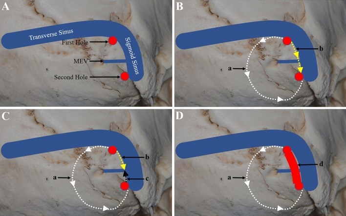
Fig. 6.
Schematic diagram of MEV treatment at the internal opening. A Two bone holes were drilled. One bone hole was located at the transverse sigmoid sinus junction (First Hole), and the other was located at the outermost edge of the exposed bone flap and above the sigmoid sinus entering the jugular bulb (Second Hole). B The medial bone flap can be milled directly with a milling cutter (a), and the lateral bone flap can be milled from the top to the bottom with a milling cutter (b). In the absence of bleeding, the flap can be milled directly. C In cases showing bleeding, the milling is stopped, the milling cutter is taken out, and the remaining bone flap is milled from the bottom to the top to connect the whole bone flap (c). D When the diameter of the MEV is larger (> 4 mm) as indicated by preoperative CT, the lateral bone flap should be carefully ground and removed (d), fully exposing the MEV and protecting the integrity of the junction between the MEV and sigmoid sinus. First Hole and Second Hole, red circles; a, white dashed line with arrow; b, yellow dashed line with arrow; c, black dashed line with arrow; d, red arch (colour figure online)

