Figure 7.
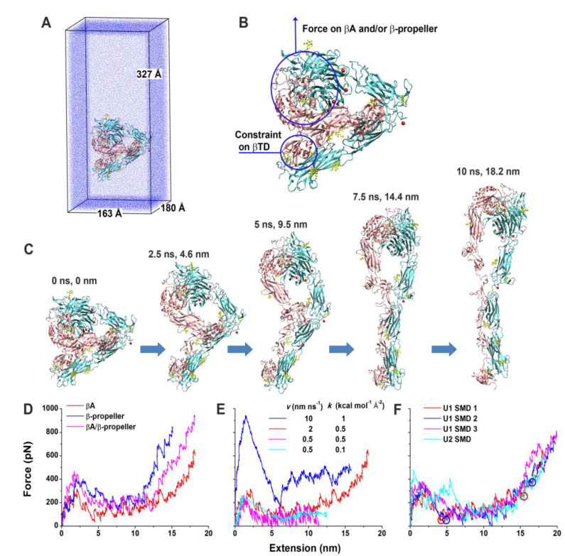
SMD simulations of the integrin αvβ3 unbending under an external force. (A) U1 in the enlarged water box for unbending simulations. (B) Illustration of force application on the head and constraint on the βTD in the SMD simulations of U1 and U2. (C) Snapshots of a representative unbending process (U1 SMD 1) taken at indicated times and extensions. (D) Force-extension curves in the constant-velocity SMD simulations of U1 by pulling the βI and β propeller domains with a 2 nm ns−1 pulling speed and a 0.5 kcal mol−1 Å−2 spring constant. (E) Force-extension curves in the constant-velocity SMD simulations of U1 by pulling the βI domain with indicated pulling speeds and spring constants. (F) Force-extension curves for three constant-velocity SMD simulations of U1 and one constant-velocity SMD simulation of U2 with a 2 nm ns−1 pulling speed and a 0.5 kcal mol−1 Å−2 spring constant. Red and blue circles indicate respective structures along the unbending pathways from the trajectories of the U1 SMD 1 and 2 that were selected as starting structures for free MD simulations. The left two represent partially-extended structures, and the right two represent fully-extended structures. The red curves in panels D–F are all for the U1 SMD 1. Reprinted with permission from ref. [194].

