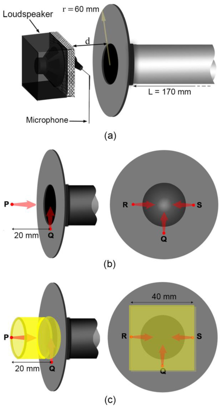
Figure 3.
(a) Schematic showing default configuration of loudspeaker and microphone used to make gamma measurements (C1); (b) P, Q, R, and S indicate the locations and orientations of the loudspeaker and microphone in C1 to C5; (c) for C6 to C10, similar P, Q, R and S, but now with acoustic foam applied (indicated in yellow): C6, C7, and C8 utilize a hollow cylindrical foam (left) while C9 and C10 have a foam ‘cap’ filling in the space between the transducers and flange (right).

