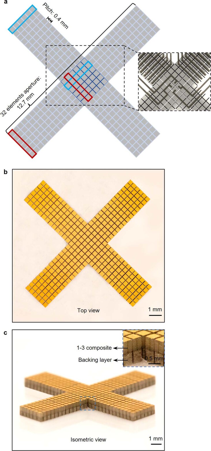
Extended Data Fig. 1. Schematics and optical images of the orthogonal imager.

a, The orthogonal imager consists of four arms, in which six small elements in one column are combined as one long element, and a central part that is shared by the four arms. The blue and red boxes label a long element integrated by six small pieces in each direction. The number of elements in one direction is 32. The pitch between the elements is 0.4 mm. Optical images in top view (b) and isometric view (c) showing the morphology of the orthogonal array. We used an automatic alignment strategy to fabricate the orthogonal array by bonding a large piece of backing layer with a large piece of 1-3 composite and then dicing them together into small elements with designed configurations. Inset in c shows the details of the elements. The 1-3 composite and backing layer have been labelled.
