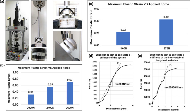
Fig. 5.
Photo of the setup to perform mechanical tests and biomechanical results of shear compressive test, torsional test, and subsidence tests from quasi-static simulation. a By using a material test machine (MTS 370, MTS System Corporation, MN, USA) and MTS torsional load cells (662.18H-05, Axial capacity: 25 KN, Torsional Capacity: 250 N-m), failure of the implants was evaluated. b The maximal plastic strain of axial compressive test under 2000N, 2400N, and 2600N respectively. c Maximum plastic strain of torsional test under 1400N and 1875N respectively. d The loading-displacement graph from the subsidence test for calculating the stiffness of the system. e The loading-displacement graph from the subsidence test for calculating the stiffness of the intervertebral body fusion device

