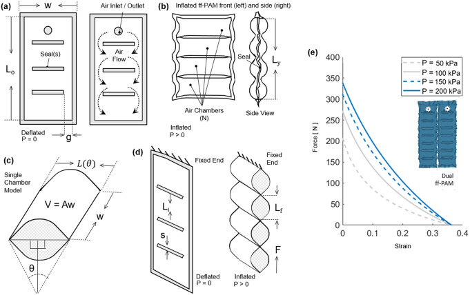
Figure 3.
(a) The frontal view representation of the ff-PAM at
 = 0, which indicates its geometries and the path of airflow within the chambers. (b) The frontal view of the ff-PAM at
 > 0 where the length and geometries are altered as a result of pressurization. (c) The cross section of a single chamber inspired by previous model iteration of inflatable pouches (Niiyama et al., 2015). (d) The isometric view of the ff-PAM in deflated and inflated states, where
 and
and
 are the initial and final lengths of
 , respectively. (e) The theoretical tensile force versus strain curve for the dual ff-PAM actuator, with eight chambers, at pressure levels of
 = 50, 100, 150, and 200
 resulting from the analytical model. Increasing pressure level result in a more stable and linear response in actuator force profile.

