. 2023 Feb 2;13(7):4222–4235. doi: 10.1039/d2ra07972k

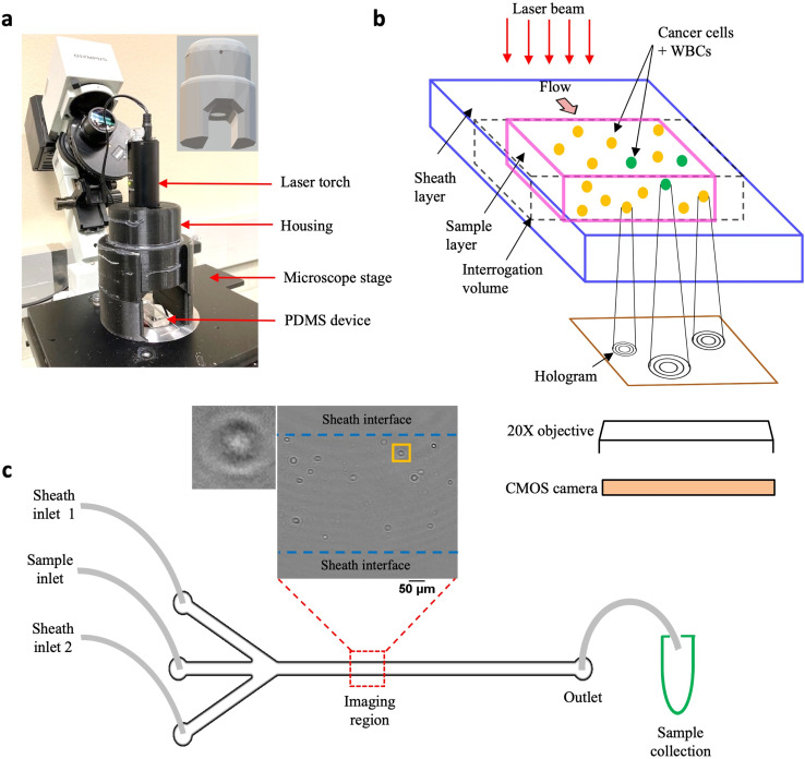
Fig. 1. Experimental setup. (a) Compact holographic assembly. The laser torch is mounted on a movable housing. Inset shows the 3D design of the housing, the circular aperture allows the laser beam to pass through, illuminating the sample coherently; (b) schematic showing in-flow holograms of a mixed sample containing MCF-7 cells and WBCs imaged with a 20× microscope objective and recorded digitally, using a CMOS, high-speed camera; (c) PDMS-based sheathing device used for flowing the sample contains two inlet channels for entry of the sheath fluid (PBS) and a central inlet for sample injection. Imaging is performed in a region near the center of the channel far away from the entrance. Inset shows a representative cleaned hologram recorded using the cHol setup, scalebar is 100 μm. By imposing a sheath flow, the cells are confined to a region away from the channel walls. Post-DHM imaging, sample is collected from the device outlet for subsequent fluorescence imaging to obtain the ground truth counts.

Fig. 1