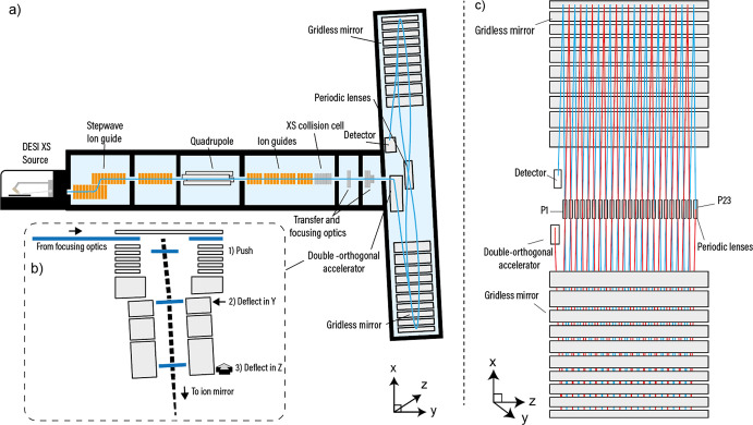
Figure 2.
Schematic of the quadrupole-MRT instrument and the MRT analyzer. (a) The overall instrument design is “Q-TOF-like” with ions introduced in the source being focused onto the main axis via a StepWave ion guide and through a quadrupole followed by a segmented quadrupole collision cell. (b) Ions from the focusing optics are (1) pushed downward (−X) so that the combination of the push voltage and the ion’s +Y velocity results in a trajectory of 6° from vertical (X axis) . The mirrors are inclined in X at 3°, so the ion path is further rotated, at (2), with a retarding field in Y. This aligns the X path rotation with the center line of the mirrors. The ions are then deflected in Z, at (3), which provides the drift across the mirrors. After each reflection in X, the ions pass through a periodic lens, which compensates for beam expansion in Z. (c) The element P1 defines the ion beam angle into the mirrors, and P23 is arranged so that it reflects the ion beam back into the mirrors, which has the effect of doubling the flight length compared with positioning the detector at P23. In this arrangement, the effective flight length is ∼48 m. P1 can be operated independently to shorten the flight path (Figure S1).

