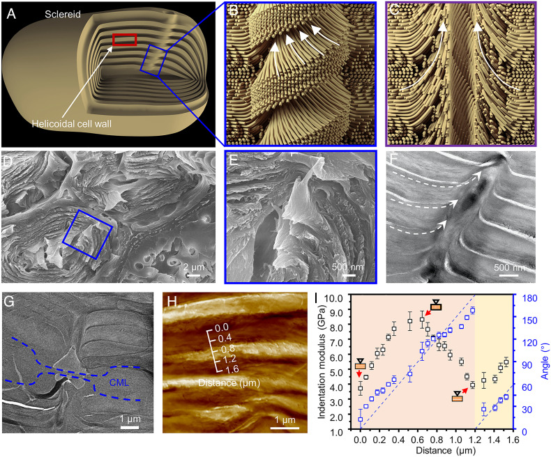
Fig. 3.
Illustration of a pit pair. (A) Schematic illustration of a sclereid with a pit embedded in its wall. (B) The schematic illustration of a pit pair embedded in the cell wall and crossing the CML. The intact pit shows a helix structure like a “screw fastener” due to the microfibrils that are winding at the edge of the pit. (C) The schematic illustration of longitudinal section of a pit pair shows that the microfibrils are all aligned at the edge of the pit, which interlocks the layers of helicoidal cell walls. To simplify this schematic, the helicoidal structure is illustrated by microfibrils with two orthometric directions. (D and E) SEM micrographs of fracture morphology shows a pit drilling to cell walls like a “screw fastener.” A higher magnification SEM image of a pit (E) demonstrates that the layers are curled and wound by the tubular pit. (F) TEM images of the longitudinal pit show that the cellulose microfibrils are all aligned along the pit and wound around the pit. (G) TEM image of the junction from a pit pair. The dashed blue areas are the CML. (H) AFM images of a cross-section of sclereids and (I) the influence of microfibril angles on indentation modulus as a function of distance over one pitch.

