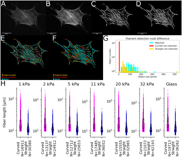
Fig 3. Example of straight versus curved filament tracing.
A: Raw image of hMSC on collagen-I coated glass. B: Result of FS2.0 filtering during pre-processing. C: Filaments found using straight filament detection. D: Filaments found using curved filament detection. E: Pixel-wise comparison of filaments found with straight and curved settings. Straight settings used as ground truth. Orange: Pixel only in straight detection. Red: Pixel only in curved detection. Blue: Pixel present in both settings. F: Object-wise comparison of filaments found with straight and curved settings. Straight settings used as ground truth. Orange: Object only in straight detection. Red: Object only in curved detection. Blue: Object present in both settings. Comparison was done with setting so that 75% of the object needs to be matched to count as same object. G: Histogram of object size for all three filament categories, colors matched to pictures. H: Comparison of all filaments in the ground truth data set for straight and curved settings. We performed a Kolmogorov–Smirnov test between each pair of conditions. All p-values are <0.001.

