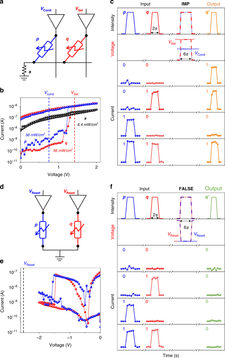
Fig. 3. “Photoresponse-stateful” strategy.
a Illustration of an in-memory IMP operation based on a set of photomemristors triggered by light stimuli. b I-V characteristics of devices s, p and q under illumination with different light intensities. c Diagram of the optical and electrical pulses applied for the IMP operation. The blue and red curves show the optical and electrical signal of devices p and q before and during the IMP operation, and the orange curves show the change in photoresponse states after IMP operations, reproducing the IMP truth table. d Illustration of an in-memory FALSE operation triggered by light stimuli based on a set of photomemristors. e I-V characteristics of devices p and q under illumination. f Diagram of the optical and electrical pulses applied for the FALSE operation. The blue and red curves show the optical and electrical signal of devices p and q before and during the FALSE operation. The black curves show the change in photoresponse states after FALSE operations, reproducing the FALSE truth table

