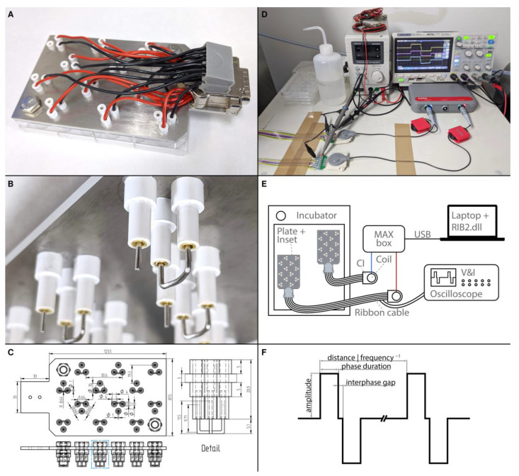
Figure 11.
Electrical stimulation setup. (A) Photograph of the electrode inset in a 24-well plate. A set of electrodes is situated within every second well. (B) Detail of the lower part of the electrode inset. Three electrode holders fit into one well. The long and thin tubes are fixed by shorter and wider tubes above (not visible) and below the metal plate. In each holder sits a gold-plated socket that is soldered to a wire. The sockets hold the curved reference electrode as well as the stimulation electrode. (C) Multiview projections (top and side) and dimensions of the base plate, electrode holders, and platinum wires. The detail shows an enlargement of the features within the blue dotted box. Photograph (D) and schematic drawing (E) of the stimulation setup. Shown are two CI stimulators connected via coil transmitters to a MAX box. An oscilloscope monitors the voltage and current of the signal. Two ribbon cables lead into the incubator and are connected to the stimulation insets. (F) Schematic illustration of the stimulation signal and its main parameters.

