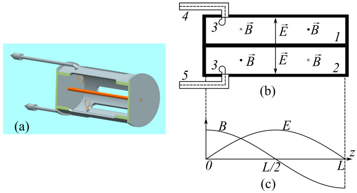
Figure 1.
Humidity sensor. (a) Sectional view of the 3D model; (b) cavity diagram: internal conductor (1), external conductor (2), magnetic coupling loops (3), cavity excitation line (4), and receiving line (5); and (c) distribution of electric E and magnetic B fields along the axis z of the cylinder.

