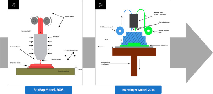
Figure 1.
(A) Schematic diagram of a 3D printer during the initial stages of the RepRap project during the early 2000s. The most distinguishing difference would be the presence of just a single extruder extruding only the single input material and the absence of a support base or support structures. (B) Schematic diagram of the more advanced continuous filament fabrication 3D technology introduced by Markforged later in 2014. The 3D printer used two extrusion nozzles to extrude the filament and lay strands of reinforcing fibers that formed the backbone. (B) Components. (i) The build platform, also called the bed, is the part of the printer where the object is printed. The build platforms may be heated to prevent warping. Increasing the temperature of build platforms also reduced deformations and shrinkage. (ii) The support base is used to keep the models fixed to the build platform while printing. (iii) The extrusion nozzle squeezes out the thermoplastic material layer-wise to form the final product. The diameter of the extrusion nozzle determines the layer thickness. (iv) The increased layer thickness reduced ductility and increased failures. (v) The liquefier head is where the thermoplastic filament is melted inside to a semimolten stage.

