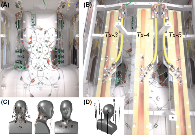
Figure 2.
Posterior views of the coil and element layout. (A) Rx subarray comprising elements 1 to 15; lateral Tx elements can be seen on the sides: 1, 2 on the left and 6, 7 on the right. (B) Full view of Tx elements 3, 4 and 5. (C) Distribution of Rx loops on the posterior (1–15) and anterior (16–20) Rx coil sections. (D) Posterior-right perspective view of the phantom showing the arrangement of Tx dipoles.

