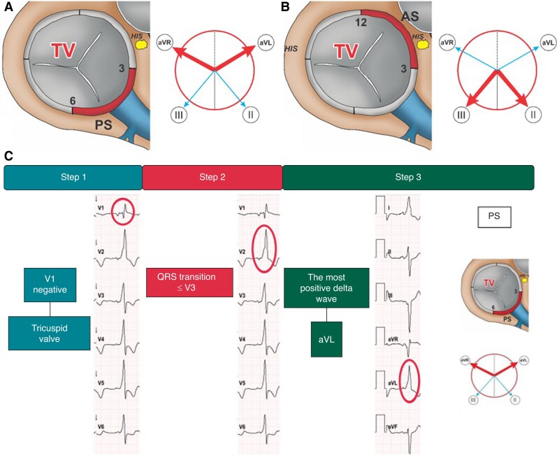
Figure 4.
Right-sided accessory pathways with QRS transition ≤ V3. Schematic representation of the TV junction region as viewed in the left anterior oblique view (60°) illustrating posteroseptal (A) and anteroseptal (B) AP-localization. The adjacent Cabrera circles indicate the corresponding leads with the most positive delta wave (bold arrow). ECG-identification of a right-sided posteroseptal AP with the EASY-WPW algorithm (C).TV, tricuspid valve; PS, posteroseptal; AS, anteroseptal; HIS, His bundle; AP, accessory pathway.

