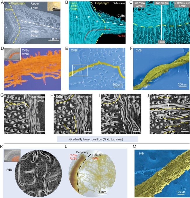
Figure 3.
Fibrous arrangement of the diaphragm. (A) Optical microscope (OM) image of one peripheral diaphragm (culm–diaphragm transition zone, side view), showing position-dependent partitions of three different fibrous zones. Inset is one real specimen. (B and C) Reconstructed 3D configurations of one peripheral diaphragm from different view directions, showing the spatially triaxial perpendicular arrangement of VBs. These position- and thickness-dependent fibrous VBs can be divided into two categories, (C, right) the RVBs at the basal periphery and (C, left) the small and thin CVBs at the upper periphery. RVB comes from deflected AVB (B, indicated by red arrow), and CVBs connect to the outside (B, indicated by white arrows). (D) False-colored peripheral diaphragm showing CVBs (top view). (E and F) SEM images of one CVB showing twisted state. (G–J) Slice projections of the ‘node culm–diaphragm’ transition zone showing position-dependent CVBs (G-I, top) and RVBs (J, bottom) at the peripheral diaphragm. The white lines (G–J) distinguish the position of the node culm and diaphragm. Thin, high-positioned TVBs from the node culm link the diaphragm, resulting in circumferential arrangement (indicated by yellow lines (G–I)). Low-positioned TVBs from the node culm link the diaphragm, resulting in radial arrangement (indicated by yellow lines (J)). (K) Slice projection of the central diaphragm showing porous IVBs (top view). Inset is the sampling site (false color). (L) Digital image of one delignified diaphragm (top view), showing dense periphery (CVBs and RVBs) and loosened IVBs at the central diaphragm. (M) SEM image of one detached IVB, showing twisted state.

