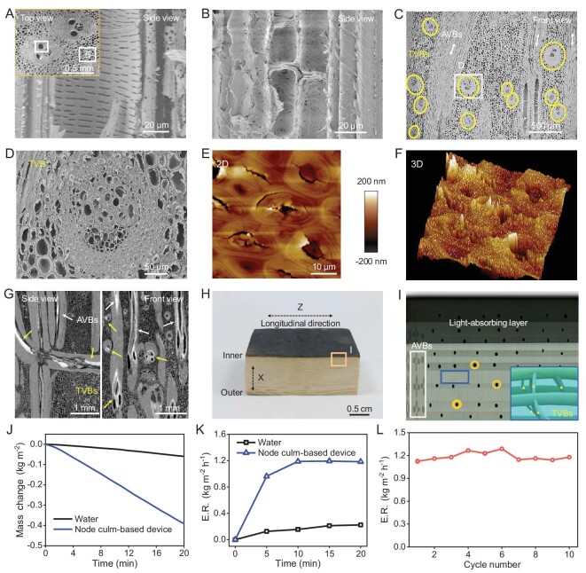
Figure 6.
Multiscale and multidirectional channels of the node culm and application. (A and B) SEM images of multiscale channels including vessels, sieve tubes, conducting cells from one AVB (A) and pits from PCs (B). Inset (A) shows sampling sites. (C and D) SEM images of TVBs indicated by circles (C), showing abundant channels (D). (E and F) AFM images of the microfibers that make up one TVB show many micro-cracks and large geomorphologic fluctuation, reflecting the loose and porous characteristics of TVBs. (G) Slice projections of the node culm (after infiltrating copper nitrate solution and drying), showing that copper nitrate substances (bright zone) occupy the channels within the TVBs (yellow arrows) and AVBs (white arrows). (H) Digital image of a water evaporation device made from one node culm. The top layer is a carbonization zone (light-absorbing layer). (I) Schematic diagram of the water evaporation device, showing multiscale and multidirectional channels for transport. The white box shows AVBs and related channels, yellow circles show pits, and blue boxes and yellow triangles show TVBs and related channels. (J) Water mass change and (K) evaporation rate (ER) during device operation under 1 sun illumination. (L) Stability of water evaporation tests of the device (working 20 min and pausing 10 min as a cycle).

