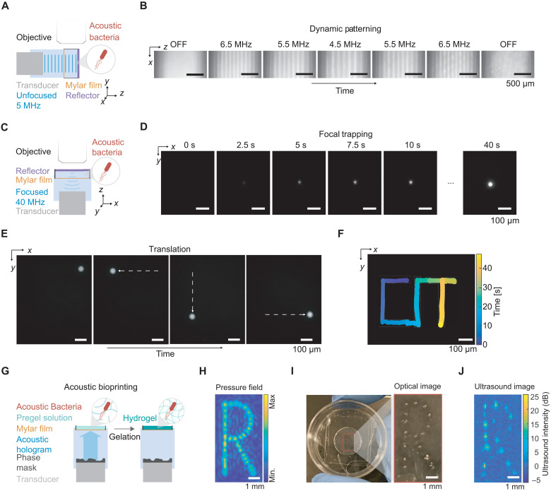
Fig. 4. Dynamic patterning and one-step bioprinting with acoustic bacteria.
(A) Diagram of the acoustic chamber setup for frequency-controlled spatial patterning. A transducer is aligned orthogonal to a glass reflector using a 3D-printed holder. The sound wave passes through a Mylar membrane, is reflected by the glass reflector, and forms a standing wave near the reflector. The sample region containing acoustic E. coli is imaged using an epifluorescence microscope. (B) Sequential fluorescence images of acoustic E. coli in the presence of an acoustic standing wave at varying frequencies. Frequencies were changed every 50 s. (C) Diagram of the acoustic chamber setup for image-guided trapping and positioning of acoustic E. coli. Imaging is performed along the axis of a focused 40-MHz transducer. (D) Sequential fluorescence images of the formation of a cluster of acoustic E. coli at the ultrasound focus. (E) Fluorescence images of a cluster of acoustic E. coli positioned at distinct locations in the x-y plane. The positioning is controlled by the translation of the transducer in the x-y plane using a micromanipulator and is guided by real-time fluorescence imaging of the bacteria. (F) Overlaid positions of the cell cluster, color-coded by time, to form a spatiotemporal pattern writing out “CIT.” (G) Diagram of the process for acoustic biofabrication. A transducer and phase mask is aligned such that the acoustic hologram is formed inside the sample chamber containing acoustic E. coli suspended in low-melt agarose solution. The gelation of the agarose is triggered to immobilize the acoustically patterned E. coli. (H) Simulated pressure amplitude generated by the acoustic hologram. (I) Acoustically patterned E. coli embedded in agarose gel. (J) Ultrasound image of acoustically patterned E. coli.

