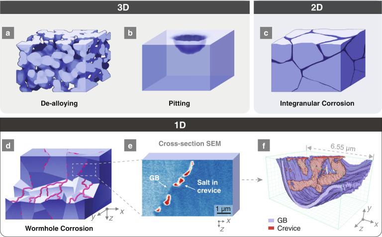
Fig. 1. Differences between 3D, 2D, and 1D corrosion.
All corrosion occurs in a top-down manner, i.e., the penetration direction through thickness is from −z to +z. a Schematic drawing of a typical bulk bicontinuous dealloying corrosion morphology. b Schematic drawing of a typical pitting corrosion morphology with the volume set as transparent. The grain boundaries (GBs) were not displayed because both intergranular and intragranular pitting can occur. c Schematic drawing of a typical intergranular corrosion morphology with the volume set as opaque. The sides of the cube display the cross-sectional views. d Schematic drawing of 1D wormhole corrosion in a polycrystalline material. The upper half is a cross-sectional view showing discontinuous dots (i.e., voids filled by molten salt) along the GBs. The bottom half is a volumetric cutaway along the GBs where the 1D percolating network of tunnels on the grain surfaces is clearly shown in red. The dark blue color in a to c indicates free space such as cracks, voids, crevices etc., while the red color in d indicates wormholes filled with molten salt. e A representative false-colored SEM image showing the cross-section of Ni-20Cr after corrosion. f FIB-SEM 3D reconstruction of the volume shown in (e). The dimension of the box is 6.6 μm (x) 3.5 μm (y) 4.1 μm (z).

