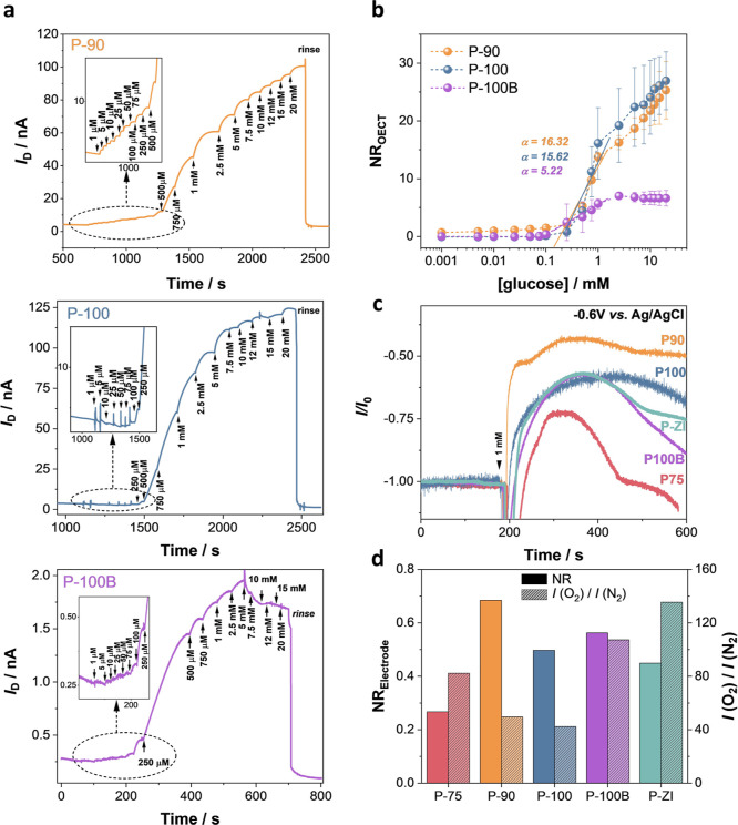
Figure 2.
Performance of n-type OECTs and electrodes as glucose sensors. (a) Real-time response of the OECT (source-drain current, ID, as a function of time) as successive amounts of glucose are added to the electrolyte. The gate and drain voltages were kept constant at +0.5 V. The OECTs were operated using a planar gate configuration, where both the channel and gate were functionalized with GOx. Insets represent the real-time response of the devices to glucose concentrations lower than 250 μM. (b) Normalized response of the OECTs (NROECT) to glucose. Error bars represent the standard deviation of at least three different devices. (c) Amperometric response of n-type conjugated polymer electrodes to 1 mM glucose. The working electrode was the n-type film functionalized with GOx, the reference electrode was Ag/AgCl, and the counter electrode was a Pt coil. The arrow represents the time point when 1 mM glucose was added into the electrolyte. (d) NRelectrode to 1 mM glucose (plain bars) and to O2 (patterned bars).

