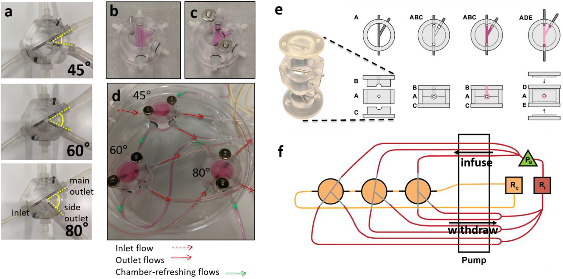
Figure 1. Design, assembly, and operation of brTEBVs.

(a) Photographs of the three brTEBV chambers with side outlet branching angles of 45°, 60°, and 80°. (b) A collagen gel containing ECs is formed in the gel-forming chamber. (c) Mandrels are moved half-way out and the inlet and outlets of the gelated vessel structure are sutured onto them. (d) Each brTEBV flow chamber has five flow connections: one for inlet flow, two for outlet flow, and two for refreshing the chamber. (e) Schematic with top and side views of brTEBV chamber assembly. The top and bottom of the gel-forming chamber (Parts B and C) are assembled with Part A with mandrels tightly joined. The EC-collagen mixture is pipetted into the inlet hole on Part B (see top view) until the mixture exits the outlet holes in Part B. After gelation at 37 °C, Parts B and C are replaced with the top and bottom of the flow chamber (Parts D and E). (f) Diagram of brTEBV operation. A multi-channel peristaltic pump simultaneously infuses the inlets from the lumen reservoir (RL), withdraws flow from the outlets of multiple brTEBVs, and replaces media in the chamber from a separate reservoir (RC). A solenoid pinch valve acts as a pulse generator (PG) and is located immediately before the inlets to provide pulsatile flow into the vessel lumen.
