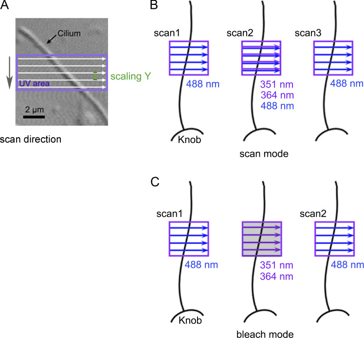
Figure 1.
UV application by scan mode and bleach mode. (A) Photomicrograph of a single cilium with Nomarski optics and the ROI of the UV irradiation area. The laser beam moves unidirectionally (white arrows) from left to right in the selected area (purple square) within the ROI. The direction of the line-by-line scan was from top to bottom in the scan area as shown by the gray arrow. The distance between the y-axis steps was determined by laser application scaling Y (green). (B) Scan mode. We inserted a UV component together with the image scan. (C) Bleach mode. The image scan and UV stimulation were independent. In this mode, the line sum parameter is ignored. Images cannot be obtained during UV stimulation (middle in C, shadow).

