Fig. 1.
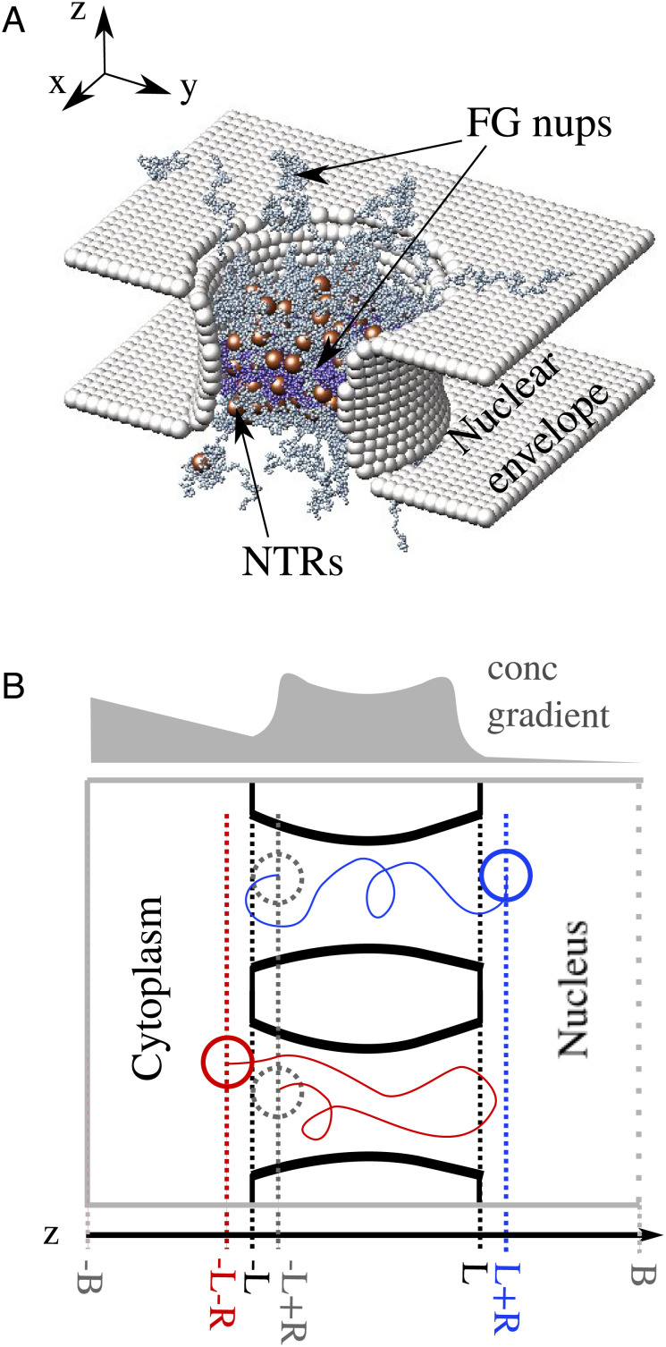
Computational model setup. (A) A snapshot from the simulation of the model of the NPC. The nuclear envelope and structural nucleoporins are represented as rigid surfaces (light grey). Two types of FG nups are grafted with 8-fold rotational symmetry to the interior of the channel, with more cohesive FG nups in the center of the NPC (purple) and less cohesive FG nups at the peripheries (grey). NTRs are modeled as spheres (brown) that interact attractively with FG nups and through steric repulsion with each other. (B) An illustration (not to scale) of the different paths followed by the center of an NTR during an entry event (blue) and an abortive event (red). We consider the NTR to have entered the pore when it crosses into the coordinate zent = −L + R (i.e. the entire volume of the NTR is contained within the NPC channel). The translocation ends once the entire volume of the NTR leaves the NPC channel, and resides either at zex+ = L + R (classified as an entry event) or at zex− = −L − R (classified as an abortive event). Simulation box boundaries are indicated in grey, the absorbing boundary (see text) is indicated by a dashed line. The length of the NPC channel is 2L = 40 nm and R = 2.5 nm. The total length of the simulation box is 120 nm. An illustrative non-equilibrium concentration profile of the NTRs is shown in light grey indicating the direction of the NTR concentration gradient; see text.

