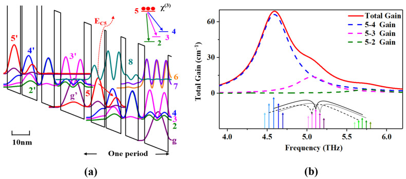
Figure 1.
(a) Conduction band diagram and wave functions of a 4.6 THz QCL structure at an electric field of 9.3 kV/cm. The layer sequence of one period starting from the injection barrier (in nm) is 5.2/9.8/1.1/11/3.5/9.2/4.8/17.3, where the barriers in bold are Al0.22Ga0.78As, the wells are GaAs and the underlined GaAs well is Si-doped. The underlined GaAs well is Si-doped to 1 × 1016 cm−3. The red arrow marks the radiative transition. The upper laser level five and the minibands (4,3,2) are shown in red, blue, pink and green, respectively. The ground state of the injector (level g’) is shown in purple. The dotted line represents the energy between the injected barrier and the upper state. The parasitic levels (8,7) are shown in deep cyan, light purple and orange, respectively. Inset: the laser transition is from the bounded level 5 to the miniband consisting of levels 4, 3 and 2. (b) Gain simulation of designed band. Inset: corresponding four-wave mixing process.

