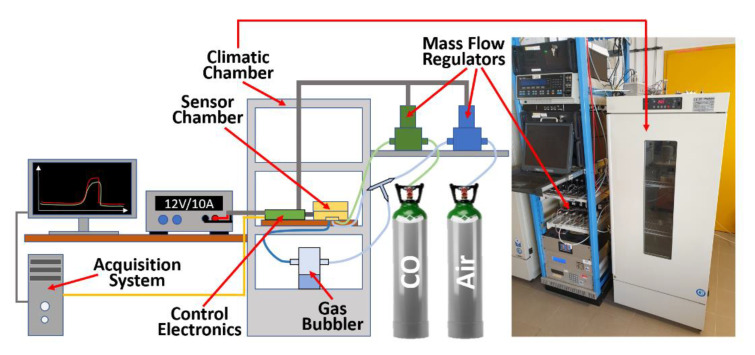
Figure 2.
Sketch of the experimental set-up. Left, schematics of the sensor set-up: the air and CO (blue and green paths respectively) fluxes, precisely adjusted through two digital mass-flow regulators, are directed toward the sensor chamber; the air can also be directed inside a gas bubbler in order to obtain a desired humidity percentage. The control electronics, powered by a 12 V/10 A power supply, managed the digital mass-flow regulators, the sensor heating, and signal acquisition, allowing to monitor the experiments in real time. The acquired signals are sent to a computer (orange cable) through a serial port and plotted by custom software. Right, photograph of the actual set-up, sketched on the left.

