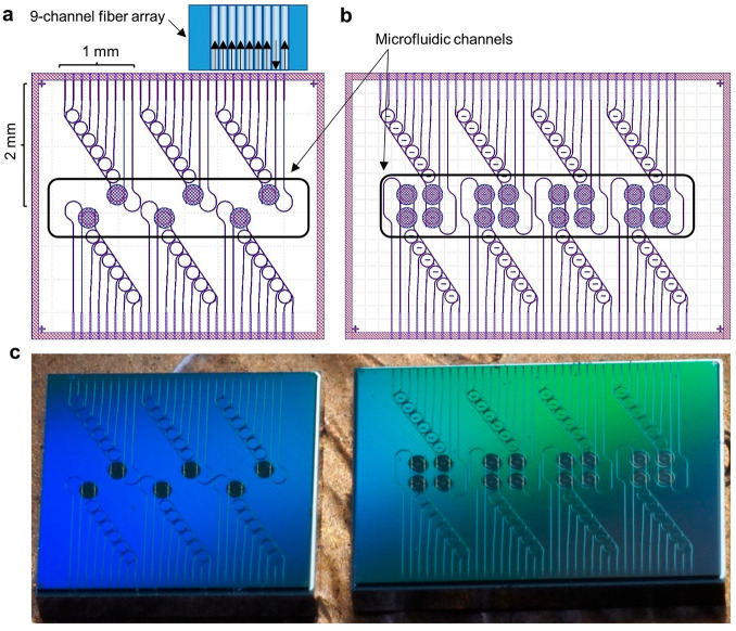
Figure 2.
(a) A 4 × 4.4 mm layout containing six sensor ring-coupled filter banks. These devices, used for bulk sensing experiments, each have a footprint of 2 × 1 mm, a single input, a transmitted output from the sensing ring T1, six filter bank outputs, and a transmitted output from the filter bank bus waveguide T2. Nine edge coupled waveguides are addressed simultaneously by a nine-channel fiber array for optical input and output. The microfluidic channel outlined in black enables fluid delivery to the sensing rings. (b) A 4 × 5.8 mm layout containing eight dual-ring-coupled filter banks used for controlled biosensing experiments. (c) Diced filter bank die as received from the vendor.

