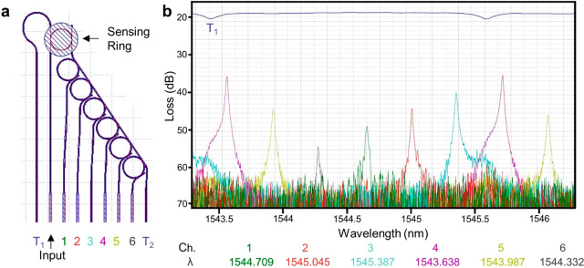
Figure 4.
(a) From left to right, the edge-coupled waveguides of a sensing ring-coupled filter bank are the transmitted output from the sensing rings bus T1, the input, the six outputs from the filter bank spectrometer rings, and the transmitted output from the filter bank bus T2. (b) Example spectra from a sensing ring-coupled filter bank. The transmitted output T1 carries the resonance notch from the sensing ring. Likewise, the transmitted output from the filter bank bus waveguide T2 is composed of the sensing resonance peak and the resonance notch for each spectrometer ring (not shown). The signal coupled to the filter bank bus waveguide must pass each of the spectrometer rings 1 through 6 in sequence. When the wavelength of light in the filter bank bus waveguide is identical to the resonant wavelength of a filter bank ring, the resonance notch is observed in the transmitted signal T2 and a corresponding peak is observed in the output for that spectrometer channel. The height of the spectrometer channel peak is inversely related to the difference between the resonance wavelengths of the spectrometer and sensing ring.

