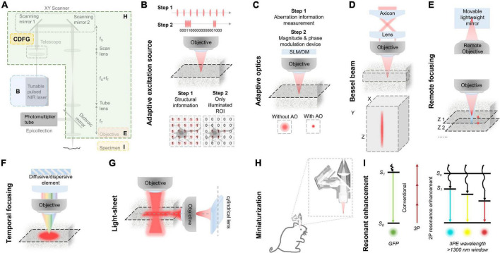
FIGURE 4.
Various improvements in classic three-photon microscopy (3PM) configuration. (A) Multiple methods to optimize the performance of 3PM from various perspectives. Different enhancement methods focus on different parts of a 3PM system. (B) Simplified schematic of the MPM system with AES. Two steps for the adaptive process. Step 1: Structural images are first captured to acquire the regions of interest (ROI, e.g., the cell body of a neuron) by uniform pulse train. The ROIs information is converted to a digital binary (“0” or “1”) sequence in the time domain and then the ROI information was encoded into the laser pulse pattern. Step 2: The pulse train, which is matched to the sample under study, is amplified to a high pulse energy and launched into the scanning system. With synchronization of scanning and excitation source, the AES only illuminates the ROIs. Gray shadow show ROI morphology. (C) A simplified schematic of modules and effect of the AO system. There are two steps for the adaptive optics. Step 1: The focus sensing module measures aberration information. Step 2: The module corrects aberration through magnitude and phase modulation device, such as SLM or DM. With AO correction, the optical resolution in focus was enhanced comparing with the absence of AO correction. (D) Top, a simplified schematic representation of an axicon-based Bessel module. Bottom, the Bessel focus exhibits an axial elongation characterized by a needle-like distribution of optical intensity in the XYZ plane. (E) Simplified schematic diagram of remote focusing strategy utilized in an imaging system. The strategy typically encompasses a remote objective and a movable lightweight mirror. Without moving the imaging objective and sample, The focal plane can be adjusted by translating the lightweight mirror. A fast actuator can move the mirror at high speed, enabling rapid axial scanning (Z1 to Z2). (F) Simplified schematic of temporal focusing strategy used in excitation optical path of an imaging system. This strategy involves incorporating a diffusive or dispersive optical element, such as a grating, into a plane conjugate to the objective focal plane. (G) Simplified schematic diagram of light-sheet strategy used in excitation optical path of an imaging system. Generally, light-sheet illumination generated by cylindrical lens on illumination path to achieve widefield imaging. The imaging objective is positioned perpendicular to the illumination objective and focuses on the light sheet to obtain a fluorescence signal. The emitted fluorescence is detected by the different objectives. (H) Head-mounted 3PM in a freely behaving rat/mouse. Magnified views of miniaturization configuration of 3PM in dashed box. Adapted with permission from Klioutchnikov et al. (2020). (I) Principle of multi-color 3PM. Schematics for simultaneous multi-color 3P excitation of a green (to S1, conventional excitation) and a cyan/yellow/red (to Sn, with 2P resonance enhancement) fluorophore with 1,340-nm excitation. The wiggly arrows indicate non-radiative relaxation. Adapted with permission from Rodríguez and Ji (2021).

