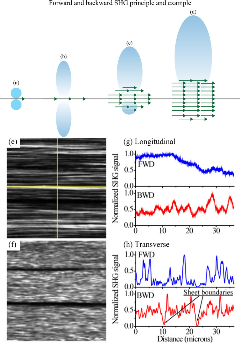
Fig. 7.
Radiation pattern for different dipole configurations in the focal volume. (a) A single dipole, indicated by the green arrow, creates equal F-SHG and B-SHG (F/B = 1). (b) Several dipoles in the same plane also create the same amount of SHG signal in the forward and backward direction (F/B = 1). (c) The coherent contribution of many induced dipoles packed in the optical direction will generate a strong forward SHG signal and a weak backward SHG signal (F/B > 1). (d) For a bulk material, only a strong forward SHG signal is present with a negligible amount of backward SHG. Adapted under CC BY-SA 4.0 from BP-Aegirsson. Forward (e) and backward (f) SHG images of fascia. Panels (g) and (h) respectively represent longitudinal and transverse intensity profiles (with respect to the fibrillar axis (horizontal axis)), as depicted by the yellow crosshair in (e), taken in forward (blue) and backward (red) direction. In the backward direction, the sheet boundaries are easier to spot than in the forward SHG image. Extracted from Rivard et al. (2010)

