
Figure 3.
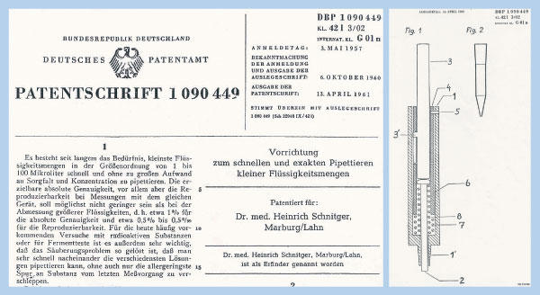
(Left) The patent application for the micropipette. The upper part of the first page and the introduction are shown. (Right) The design principle of the modern micropipette from the patent. In part 1, note the handle (3) pushing the piston (6). Its nose (3′) runs in a slit of the first concentric mobile cylinder. The piston (6) is spring-loaded and runs to the end of the housing (1). The inner cylinder is also loaded by a stronger spring (7), which can be pushed down with increased pressure when the nose (3′) hits the lower end of the slit. Part 2 shows the principle construction of the plastic tip, which receives an exact quantity of fluid when the handle held at the lower end of the slit is released.