Vengrenyuk et al. 10.1073/pnas.0606310103. |
Supporting Appendix
Stresses and Displacements in a Fibrous Cap Containing a Perfectly Bonded Rigid Spherical Inclusion
The stress-free boundary conditions at ![]() are
are
![]()
![]() ,
, ![]()
![]() ,
,
![]()
![]()
Assuming perfect bonding at the rigid spherical inclusion-tissue interface, one requires
u
= 0 atThe condition that the normal stress in the plate in the x direction tend to a uniform stress T0 as x tends to ![]() is given by
is given by
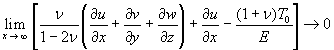 . [4]
. [4]
1. Stress Functions
A general solution of the Eqs. 1-4 is represented as a combination of six harmonic functions![]() . Components of the displacement vector u(
. Components of the displacement vector u(![]() ) are expressed in terms of these functions as follows:
) are expressed in terms of these functions as follows:
![]()
![]()
![]()
![]() [5]
[5]
![]()
![]()
where
![]() [6]
[6]
![]() ,
,
and ![]() and G denote Poisson's ratio and the shear modulus respectively. The displacement and stress fields derived from these harmonic stress functions satisfy the governing Eq. 1 in the absence of body forces.
and G denote Poisson's ratio and the shear modulus respectively. The displacement and stress fields derived from these harmonic stress functions satisfy the governing Eq. 1 in the absence of body forces.
2. Solution of the Problem in the Absence of an Inclusion
First, we choose harmonic functions ![]() and
and ![]() in the following form:
in the following form:
![]()
![]() [7]
[7]
![]() ,
,
where![]() ;
; ![]() and
and ![]() are Legendre functions of the first kind of order n and associated Legendre function of the first kind of order n and degree m, respectively. Substituting expressions 7 for harmonic functions
are Legendre functions of the first kind of order n and associated Legendre function of the first kind of order n and degree m, respectively. Substituting expressions 7 for harmonic functions ![]() and
and ![]() into expressions 5 one can calculate the corresponding displacement and stress fields:
into expressions 5 one can calculate the corresponding displacement and stress fields:
![]() [8]
[8]
![]() , [9]
, [9]
where E is Young's modulus.
Expressions 8 and 9 represent a solution of the problem of a thick plate under uniaxial tension ![]() parallel to the x axis in the absence of an inclusion.
parallel to the x axis in the absence of an inclusion.
Eq. 9 shows that this solution gives no traction at the surfaces of the plate ![]() . The components of the displacement on the inclusion surface are
. The components of the displacement on the inclusion surface are
![]()
![]() [10]
[10]
![]()
To satisfy zero displacement boundary conditions at the inclusion interface (3) when an inclusion is present, we construct auxiliary stress functions using suitable harmonic functions such that they would yield no traction on the plate surfaces
![]() [11]
[11]
and satisfy the following boundary conditions at ![]() :
:
![]()
![]() [12]
[12]
![]()
Expressions 11 and 12 are split into an axisymmetric part that does not depend on j and an asymmetric part that is a function of j.
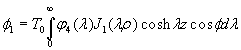
3. Axisymmetric Solution
First, we construct the auxiliary stress functions for the case of a stress distribution that is axisymmetric about the z axis as follows:
![]() ,
,![]() [13]
[13]
where ![]() are unknown coefficients of the spherical stress functions,
are unknown coefficients of the spherical stress functions, ![]() are Legendre functions, and
are Legendre functions, and
 ,
, [14]
[14]
 ,
, 
where ![]() is a Bessel function of the first kind of the zero order and
is a Bessel function of the first kind of the zero order and ![]() are arbitrary cylindrical functions of
are arbitrary cylindrical functions of![]() .
.
The integral relation
 [15]
[15]
allows one to express the spherical stress functions (13) in cylindrical coordinates and rewrite the stress-free boundary conditions at ![]() (11) as follows:
(11) as follows:
![]()
![]()
![]()
![]()
![]()
![]()
![]()
![]() [16]
[16]
The next step is to express cylindrical functions ![]() in terms of the spherical functions (13) by applying Hankel transforms to the stress free boundary conditions (16) and solving the four linear algebraic equations simultaneously for
in terms of the spherical functions (13) by applying Hankel transforms to the stress free boundary conditions (16) and solving the four linear algebraic equations simultaneously for![]() :
:
![]()
![]()
![]()
![]()
![]()
![]()
![]()
![]()
![]()
![]()
![]()
![]()
![]()
![]()
![]()
![]()
![]()
![]()
![]() , [17]
, [17]
where
![]()
To satisfy remaining boundary conditions at the inclusion interface (12), one has to express the cylindrical functions (14) in spherical coordinates using following relations:
![]() [18]
[18]
![]()
The resulting expansions of the cylindrical functions ![]() and
and ![]() (14) are given by
(14) are given by
![]() ,
, ![]() , [19]
, [19]
where coefficients ![]() and
and ![]() are determined by
are determined by
 ,
,  , [20]
 ,
, .
.
Substituting ![]() given by Eq. 17 into Eqs. 20, expressions for
given by Eq. 17 into Eqs. 20, expressions for ![]() and
and ![]() can be obtained in terms of the unknown spherical coefficients
can be obtained in terms of the unknown spherical coefficients![]() . These expressions contain integrals with respect to
. These expressions contain integrals with respect to ![]() that have to be evaluated numerically.
that have to be evaluated numerically.
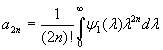
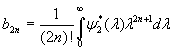
Finally, using stress functions (5) and satisfying boundary conditions (10), one can obtain the resulting system for the axisymmetric case
![]()
![]() [21]
[21]
![]()
![]() [22]
[22]
Equating coefficients of each Legendre function ![]() in Eq. 21 or its derivative
in Eq. 21 or its derivative ![]() in Eq. 22 to zero, one obtains a system of linear equations for the unknown coefficients of the spherical harmonics
in Eq. 22 to zero, one obtains a system of linear equations for the unknown coefficients of the spherical harmonics![]() . The axisymmetric solution of the problem (1-4) is determined by truncating and solving this system. After solving for the coefficients, one can calculate the stresses and deformations at any point within the plate.
. The axisymmetric solution of the problem (1-4) is determined by truncating and solving this system. After solving for the coefficients, one can calculate the stresses and deformations at any point within the plate.
4. Asymmetric Solution
For the asymmetric problem, the pure shear spherical and cylindrical harmonics are defined by
![]() ,
, ![]() ,
, ![]()
![]() ,
, ![]() [23]
[23]
 ,
,
 ,
, 
 [24]
[24]
 ,
,
 ,
, 
 ,
,
where ![]() and
and ![]() are unknown coefficients of the spherical harmonics;
are unknown coefficients of the spherical harmonics; ![]() and
and ![]() are arbitrary functions.
are arbitrary functions.
In a similar procedure to that described in the previous section, one satisfies boundary conditions 11 and 12 by using relations 15 and 18. The final equations for the asymmetric case are
![]()
![]()
![]()
![]() [25]
[25]
![]()
![]()
![]()
![]()
Equating coefficients of each Legendre function ![]() in Eq. 25 to zero, one obtains a system of linear equations. The asymmetric solution of Eqs. 1-4 is determined by solving the linear simultaneous equations for the parametric coefficients of the spherical harmonics
in Eq. 25 to zero, one obtains a system of linear equations. The asymmetric solution of Eqs. 1-4 is determined by solving the linear simultaneous equations for the parametric coefficients of the spherical harmonics![]() . Solving for the coefficients, one can calculate the stresses and deformations corresponding to the asymmetric case at any point within the plate.
. Solving for the coefficients, one can calculate the stresses and deformations corresponding to the asymmetric case at any point within the plate.
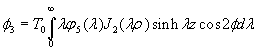
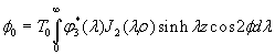
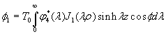
5. The Combined Solution
Final expressions for the displacement and stress fields are given by
u = u1 + u2![]() ,
,
si = si1 + si2![]() ,
,
where u1, si1 and u2, si2 represent the axisymmetric and the symmetric parts, respectively.
Supporting Methods
Micro-CT Imaging Technique.
Formalin-fixed human coronary segments (»25 mm length, n = 24) obtained at autopsy were scanned by using a GE Healthcare eXplore SP PreClinical Specimen micro-CT acquisition and analysis system. The coronary samples were kept in PBS at 4°C and stabilized at room temperature for 30 min prior scanning procedure. For image acquisition, x-ray projections were generated from the sample each 0.5° increments of rotation, obtaining 720 consecutive views with maximal 7-mm resolution. Five exposures by projection were used to produce high-contrast, low-noise images. The raw images were corrected for possible pixel defects in the digital detector by using bright and dark fields, and a standard reconstruction algorithm (Feldkamp cone beam) included in the GE acquisition system was applied to generate 3D volumes from the planar x-ray projections. Densities within the volumes were calibrated by using a phantom containing hydroxyapatite (a main component of bone mineralized phase), air, and water, which was included with each scan.Initial reconstructions of the whole volumes were carried out at 35-mm voxel resolution. Because of computational limitations to handle digital data sets higher than 800 MB, the digital volumes were sectioned in consecutive volumes of interest consisting of the whole vessel circumference and »3 mm in height, which were reconstructed at 7-mm resolution, resulting in eight to nine sections per sample. Density-calibrated images were segmented by using the global threshold method built-in MicroView visualization and analysis software (GE Healthcare; Version 2.1.2). The presence of mineral, soft tissue, lipid, and air in the vessels was distinguished by the high sensitivity of the system to the different densities on each of these compartments. Mineralized tissue particles were investigated on each volumes of interest, and isosurfaces of microcalcifications in the fibrous caps of atherosclerotic lesions were rendered by using the MicroView software.