Abstract
Purpose:
CCD cameras are employed to image scintillation and Cherenkov radiation in external beam radiotherapy. This is achieved by gating the camera to the linear accelerator (Linac) output. While a direct output signal line from the target current can be used, this approach can induce delay in the trigger signal, and potentially alter Linac performance through electrical feedback. A scintillating detector for stray radiation inside the Linac room was developed to act as an untethered trigger for camera-based dosimetry, thereby overcoming the issues of time delay and altered Linac performance.
Methods:
A scintillator coupled silicon photomultiplier detector was optimized and systematically tested for location sensitivity and for use with both X-rays and electron beams, at different energies and field sizes. Two different scintillator sizes were used for the study. Images captured using the physical trigger were compared to the stray radiation trigger. The issue of false positive event detection, due to additional neutron activated products with high energy beams, was addressed.
Results:
For X-ray beams, the detector module triggered 130–80 ns before the Linac target current signal output line. The designed circuit provided ample output voltage for the camera to trigger for distances up to 3m from the isocenter with a 6MV, 5×5cm beam, using a Ø3×20 mm3 crystal. With a larger scintillator size, the detector could be placed even beyond 3m distance. False positive triggering was reduced by a coincidence detection scheme. Negligible fluctuations were seen in time-gated imaging of Cherenkov intensity on a body phantom, when comparing directly connected vs this remote triggering approach.
Conclusion:
This scintillator-diode trigger can be used for remote Cherenkov imaging or remote scintillator dosimetry imaging during radiotherapeutic procedures. Moreover, the module overcomes the delay caused by wire-based triggering and solves the issue of false triggering from stray radiation.
1. Introduction:
Diagnostic devices that are synchronized to the medical linear accelerator (linac) can be used to track events resulting from linac radiation pulses. Medical linacs deliver X-ray or electron beam pulses of 3–6 μs duration with a 60–360 Hz repetition rate. One useful feature of this low duty cycle delivery is that light emitted from scintillators placed in the beam can be sampled for dosimetric purposes, at this same frequency, thereby removing considerable ambient background.1 Time-gated optical imaging can also be used to image Cherenkov Radiation (CR)2,3 The underlying principle in these diagnostic measurements makes use of the pulsed nature of linac output and time-gated image acquisition. As a side effect of the beam generation and dose delivery, pulsed stray X-ray radiation is emitted from the beam target. Minor X-ray leakage from the linac gantry is also expected. In both cases, the waveform of the stray radiation follows the waveform of the primary X-ray or electron beam, and thus can be used for remote beam detection. In this work, a trigger circuit for detection of stray radiation was prototyped and optimized. Finally, the detector was compared against wired triggering.
For gating purposes, a long BNC cable can be used to connect the target current signal port (TargI) or the Klystron Voltage (KlyV) port from the linac control unit to the external trigger port of the camera. One of the major problems with such a setup is that it induces a temporal delay in the trigger signal as it propagates down the wire. This delay can manifest itself as decreased scintillation or Cherenkov intensity during time-gated acquisition, since the camera would not capture for the whole duration of the pulse. A physical trigger cable can also provide unwanted electronic feedback to the linac, which can potentially alter the charge distribution or current flow at the target. It is also common that manufacturer may limit access to the linac’s control unit, thereby making time-gated image acquisition hard to achieve.
To overcome these issues, remote triggering from a stray radiation detector, which works in avalanche mode, was proposed. A silicon photomultiplier tube (SiPM) module was coupled to a scintillator which operates by detection of stray radiation inside the linac room. As ionizing radiation impinges on the scintillator crystal, optical radiation is emitted from the crystal. These scintillation photons are then detected by the SiPM module and converted into a voltage pulse by current-to-voltage amplifier. This voltage pulse can be used to trigger the time-gated camera. This approach requires no physical wire connection to the linac and has the potential to be superior in terms of time resolution.
2. Materials and Methods
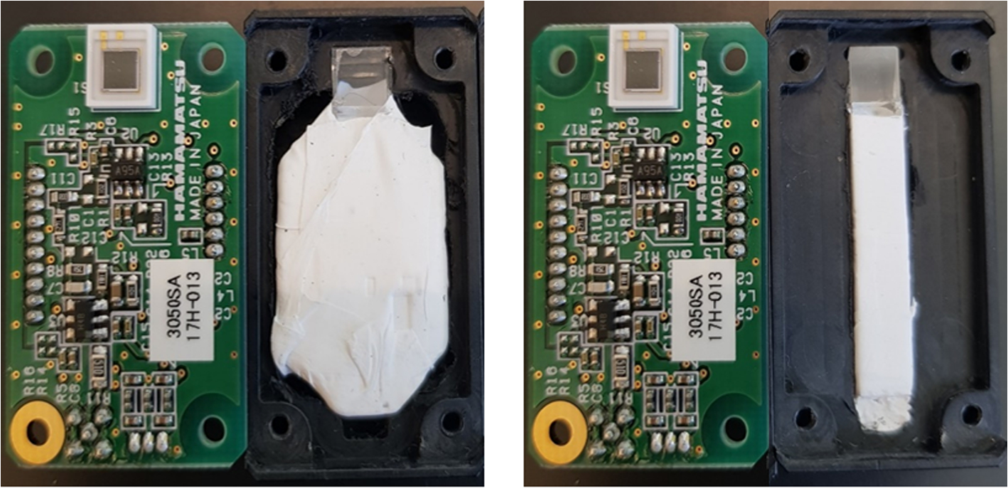
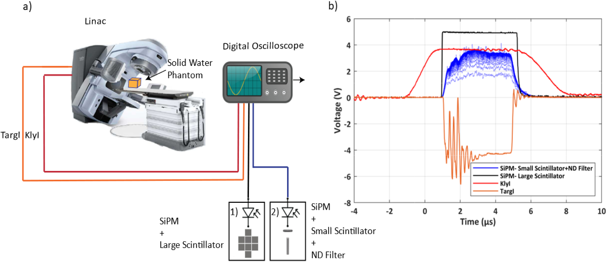
A schematic of the experimental setup in shown in Figure 1. A Bi4Ge3O12 (BGO) crystal (EPIC Crystal, Kunshan, China) was coupled to C13365–3050SA silicon photomultiplier (SiPM) module (Hamamatsu Photonics, Shizuoka, Japan) to detect stray X-ray radiation from medical linac (Varian 2100CD, Palo Alto, USA). The crystals were wrapped in white Teflon tape and optically shielded by an opaque plastic enclosure to eliminate stray light detection. Two different configurations of the scintillating crystal were used. For quantitative assessment of the peak output voltages at various room locations and beam parameters, we used a smaller scintillator (Ø3×20 mm3) with an additional thin neutral density (ND) filter (optical density 1.0) between the crystal and detector. In the second configuration, an array of eight 5×5×5 cm3 BGO crystals was employed. This configuration produced a scintillation light output that always saturated the SiPM sensor irrespective of the trigger’s location within the room, beam energy, or beam size. Such a configuration would be the most effective as a trigger for the camera. We assume 2.5 V threshold to indicate the leading edge of trigger signal, which is half of the maximum amplitude that can be provided by SiPM module and is also compatible with the voltage level of transistor-transistor logic (TTL). Unlike vacuum photomultipliers, performance and operation life of SiPM detectors is not severely altered at these saturated operating conditions. SiPM module output was recorded along with Klystron current (KlyI) and Target current (TargI) service signals from linac by a 300 MHz oscilloscope (Pico Technology, St Neots, United Kingdom). Characteristic waveforms and timing of these signals are shown in Figure 2 (b). During measurements, a 30×30×15 cm block of Solid Water (Sun Nuclear, Melbourne, USA) was used as a dose delivery phantom.
Figure 1.

Left: SiPM + An array of eight 5×5×5 cm3 BGO crystals. Right: SiPM+ smaller scintillator (Ø3×20 mm3). The scintillators were wrapped in white Teflon tape to increase light collection efficiency.
Figure 2.

(a) A schematic of the experimental setup. A medical linear accelerator was used to deliver radiation to a 30×30×15 cm block of solid water. Two synchronization signals, Klystron current (KlyI) and Target current (TargI) from the linac were connected to a digital oscilloscope using a BNC cable. The two different scintillation configurations were used; 1) An array of eight 5×5×5 cm3 BGO crystals; 2) (Ø3×20 mm3) BGO Crystal and a thin neutral density filter (OD 1.0). (b) Characteristic waveforms and timing of X-ray trigger output and linac service signals (KlyI and TargI), are shown in persistence mode (total number of pulses: 100).
Cherenkov emission from a breast phantom was also captured and compared using the TargI and the detector as a trigger signal for an intensified CMOS camera (DoseOptics, NH, USA). In this study, YAG: Ce scintillator was employed. The resulting images were then compared. Finally, the detector was used in a simulated total skin electron therapy delivery.
3. Results
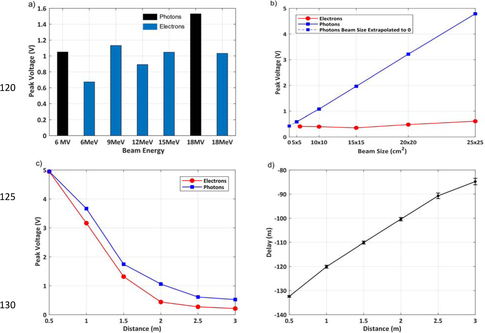
First, we measured the relative detector output for 10×10 cm2 radiotherapeutic beams of different energies and types (photons vs. electrons). The detector was placed at 2.0 m from the isocenter. The resulting output amplitudes are plotted for each available beam energy in Fig 3(a). The average amplitude of the detector with the small scintillator was 1.1±0.4 V. The peak voltage ratio of the large scintillator to the small scintillator detector was found to be approximately 70. Using this conversion ratio, the theoretical peak voltage of large scintillator detector comes out to be approximately 77 V, well above the 2.5 V threshold level.
Figure 3.

(a) Detector output as a function of different beam energies at 2.0m away from the isocenter with a beam size of 10×10cm2. (b) Detector output as a function of beam size at 2.0m away from the isocenter with a 6MV and a 6MeV beam. (c) Detector output as a function of distance from the isocenter for a 6MV/6MeV, 10×10cm2 beam. (d) Delay between TargI and Detector Output as a function of distance of the detector from the isocenter for a 6MV, 10×10cm2 beam
To assess the detector output for different beam sizes, we placed the detector 2.0 m from the isocenter and varied the beam size from 5×5 to 25×25 cm2. 6 MV and 6 MeV beams were used for photons and electrons, respectively. While the photon beam shows a linear increase in detector output with increasing beam size, the increasing electron beam sizes result in only a slight increase in detector output. Extrapolated amplitude of approximately 0.4 V at zero beam size (Fig 3d) suggests a presence of stray radiation even with fully closed jaws during both electron and photon deliveries. This signal is most likely present due to radiation leakage from the bending magnet assembly in the gantry. Amplitude of this signal from small scintillator detector corresponds to a theoretical amplitude of 28 V in large scintillator detector, which is again well above the threshold level.
Figure 3(c) shows the detector output as a function of the distance of the detector from the isocenter. 6 MV and 6 MeV 10×10 cm2 beams were used for photons and electrons, respectively. The detector output decreases as the detector moves away from the isocenter. At 3.0m an amplitude of 0.5 V (6 MV photon beam) or 0.2 V (6 MeV electrons) was detected, corresponding to theoretical 35 V and 14 V amplitudes in large scintillator detector, respectively. Therefore, even at 3.0 m from the isocenter, the detector provides enough voltage for the camera to trigger.
Figure 3(d) shows the time delay between the detector output and the TargI signal as a function of the distance of the detector from the isocenter of the linac. A 6MV photon beam was used for this experiment. At 0.5 m distance, the stray radiation detector signal would trigger 132 ns before the TargI signal. As the distance between the detector and the isocenter increases, this time difference decreases to 85 ns at 3.0 m distance.
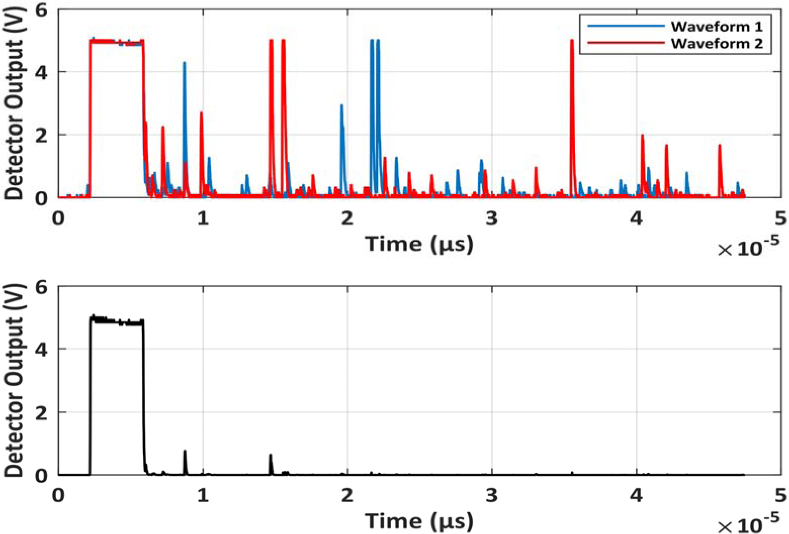
Delayed, short yet intense scintillation pulses were detected after each 18 MV photon pulse and to a lesser extent, after 15 MeV and 18 MeV electron beam pulses. These pulses, generated most likely by neutron activation products, may in practice result in false positive triggering of the time-gated equipment. A coincidence detection mechanism can be employed to overcome this issue. Coincidence detection modality was simulated by using multiple waveforms, produced by 18 MV pulses in large scintillator detector at 2.0 m distance. In Figure 4 (Top), two representative waveforms were superimposed in time and their amplitudes multiplied. This method may be implemented as logical AND operation on binarized signals from two independent detectors. The resulting waveform in Fig 4 (Bottom) shows that the unwanted false positive events were eliminated.
Figure 4.

Top: Scintillation response to X-ray beam pulse and additional spurious pulses after the delivery of the beam. Bottom: Multiplication of the two waveforms removes the unwanted spurious pulses. This demonstrates that logical AND function for two independent detectors can be used to eliminate the spurious pulses.
Cherenkov emission from breast phantoms was then captured using the physical trigger cable and the detector as trigger signals for an intensified CMOS camera. A 6 MV, 200 MU, 5 × 5 cm2 beam was used. The camera and detector were placed at 2 m from the phantom. Camera exposure time was set to 51 ms. Cherenkov frames were captured instantaneously after the leading edge of trigger, whereas the background frames were captured with a 10 μs delay. Cherenkov and background images were subtracted, and the individual background-subtracted frames were then summed up to produce the cumulative images. The results in Figure 5 show that the image captured using the detector visually matches the image captured using the TargI signal from the linac. A difference of <0.1% of the cumulative intensity was observed in the Cherenkov emission captured using the TargI and stray X-rays as the sources of trigger signal.
Figure 5.

Cherenkov emission captured using an intensified CMOS camera with (a) the Remote Detector and (b) TargI as trigger signals. A 6MV, 200 MU, 5×5 cm2 beam was used. (c) The difference between the images (a) and (b). The image intensity is represented as a percentage of the image intensity in 5(a). The average cumulative Cherenkov intensity between acquisitions triggered by TargI and remote detector signals differed by <0.1%.
Finally, the detector was tested during a simulated total skin electron therapy (TSET) delivery. 6 MeV, high dose rate total skin electron (HDTSe−) delivery with 36×36 cm2 beam size at isocenter was employed. The gantry head was rotated to 270° and aimed at TSET stand at 4.0 m source-to-surface distance, where the patient would normally stand upright. The detector was placed behind the gantry head with direct line of sight to the TSET stand at 5 m distance. A peak voltage of 239.5mV was observed for the small scintillator. This results in a theoretical voltage of 16.8V for the large detector, confirming the detector’s viability for a TSET setup.
4. Discussion
To act as a trigger for the camera, the detector should be able to trigger the camera independent of the beam type, energy, size used and the location of the camera in the room. Our experiments show that within the typical operating ranges of linac and large scintillator detector, the stray X-ray radiation produced ample scintillation signal that can be used for linac-synchronized time gating. For the large scintillator, a 10-fold change in detector output was observed corresponding to a 1% change in timing of the rising edge of the detector output. Depending on the location of the detector in the linac room, beam size, and beam energy, the stray radiation due to photon beams produced 1–8 times larger scintillator output than in the case of electron beams.
A linear increase in detector output was observed for increasing photon beam size, whereas for electrons, the detector output was nearly constant around 0.4 V baseline. The origin of baseline signal may be explained by a nearly constant X-ray leakage from linac head – most likely the electron bending magnet shielding – before beam collimation and shaping. Increase in signal from increasing X-ray beam size can be attributed to increased scatter from the irradiated phantom and the floor. The signal during electron beam radiation is most likely due to X-ray production in the head of the accelerator. Sources include the bending magnet, the primary collimating jaws, and the secondary electron skimmers in the cone assembly; all but the latter stay constant with chosen electron field size.
Since the amplitude of the detector output depends largely on the size of the scintillating material, one could use larger scintillator to trigger any time-gated equipment even at extreme locations inside the room. However, use of larger scintillators would result in higher probability of detecting stray β and γ-rays, generated during decay of radioisotopes that were created by [γ, n] and [n, γ] reactions in the linac head and all irradiated objects5,6. In practice, this would have resulted in false positive trigger events. We proposed and simulated a coincidence measurement technique, that minimized the possibility of false trigger events due to neutron activation.
Negligible Cherenkov intensity fluctuations (< 0.1%) were observed between images captured using the remote detector and TargI as a trigger, as illustrated in Figure 5. This validates the remote detector’s efficacy as a trigger for the capturing Cherenkov emission.
The remote trigger detector was able to provide a stable timing signal that preceded the electric signals provided by linac service ports. This can be explained by the fact that the wired connection requires a transmission line that is longer than the line-of-sight between the remote trigger detector and gantry/irradiated object. Furthermore, the stray X-rays travel at speed of light, while coaxial transmission line carries signal that is slowed down by cable-specific velocity factor. In our case, remote stray radiation detector provided trigger signal approximately 100 ns earlier than the wired connection.
5. Conclusion
Our stray radiation triggering module provides an electric signal which is perfectly synchronized to pulses of radiotherapy linac beams of various field sizes and energies. The detector is particularly useful for remote Cherenkov imaging or remote scintillator dosimetry imaging. This module overcomes the delay caused by wire-based triggering and eliminates the limitations for interfacing medical devices.
5. Acknowledgements
This work has been sponsored by National Institutes of Health research grants R44 CA199681, R01 EB023909, R01 EB024498, and P30 CA 23108.
Footnotes
Disclosure of Conflicts of Interest
The authors have no relevant conflicts of interest to disclose
7. References
- 1.Archambault L, Beddar A, Gingras L, Lacroix F, Roy R, Beaulieu L. Water-equivalent dosimeter array for small-field external beam radiotherapy. Med Phys. 2007;34(5):1583–1592. doi: 10.1118/1.2719363. [DOI] [PubMed] [Google Scholar]
- 2.Glaser A, Zhang R, Davis S, Gladstone D, Pogue B. Time-gated Cherenkov emission spectroscopy from linear accelerator irradiation of tissue phantoms. Opt Lett. 2012;37(7):1193. doi: 10.1364/ol.37.001193. [DOI] [PMC free article] [PubMed] [Google Scholar]
- 3.Čerenkov P Visible Radiation Produced by Electrons Moving in a Medium with Velocities Exceeding that of Light. Physical Review. 1937;52(4):378–379. doi: 10.1103/physrev.52.378. [DOI] [Google Scholar]
- 4.Glaser A, Zhang R, Andreozzi J, Gladstone D, Pogue B. Cherenkov radiation fluence estimates in tissue for molecular imaging and therapy applications. Phys Med Biol. 2015;60(17):6701–6718. doi: 10.1088/0031-9155/60/17/6701. [DOI] [PMC free article] [PubMed] [Google Scholar]
- 5.Fischer H, Tabot B, Poppe B. Activation processes in a medical linear accelerator and spatial distribution of activation products. Phys Med Biol. 2006;51(24):N461–N466. doi: 10.1088/0031-9155/51/24/n02. [DOI] [PubMed] [Google Scholar]
- 6.Howell R, Kry S, Burgett E, Hertel N, Followill D. Secondary neutron spectra from modern Varian, Siemens, and Elekta linacs with multileaf collimators. Med Phys. 2009;36(9Part1):4027–4038. doi: 10.1118/1.3159300. [DOI] [PMC free article] [PubMed] [Google Scholar]


