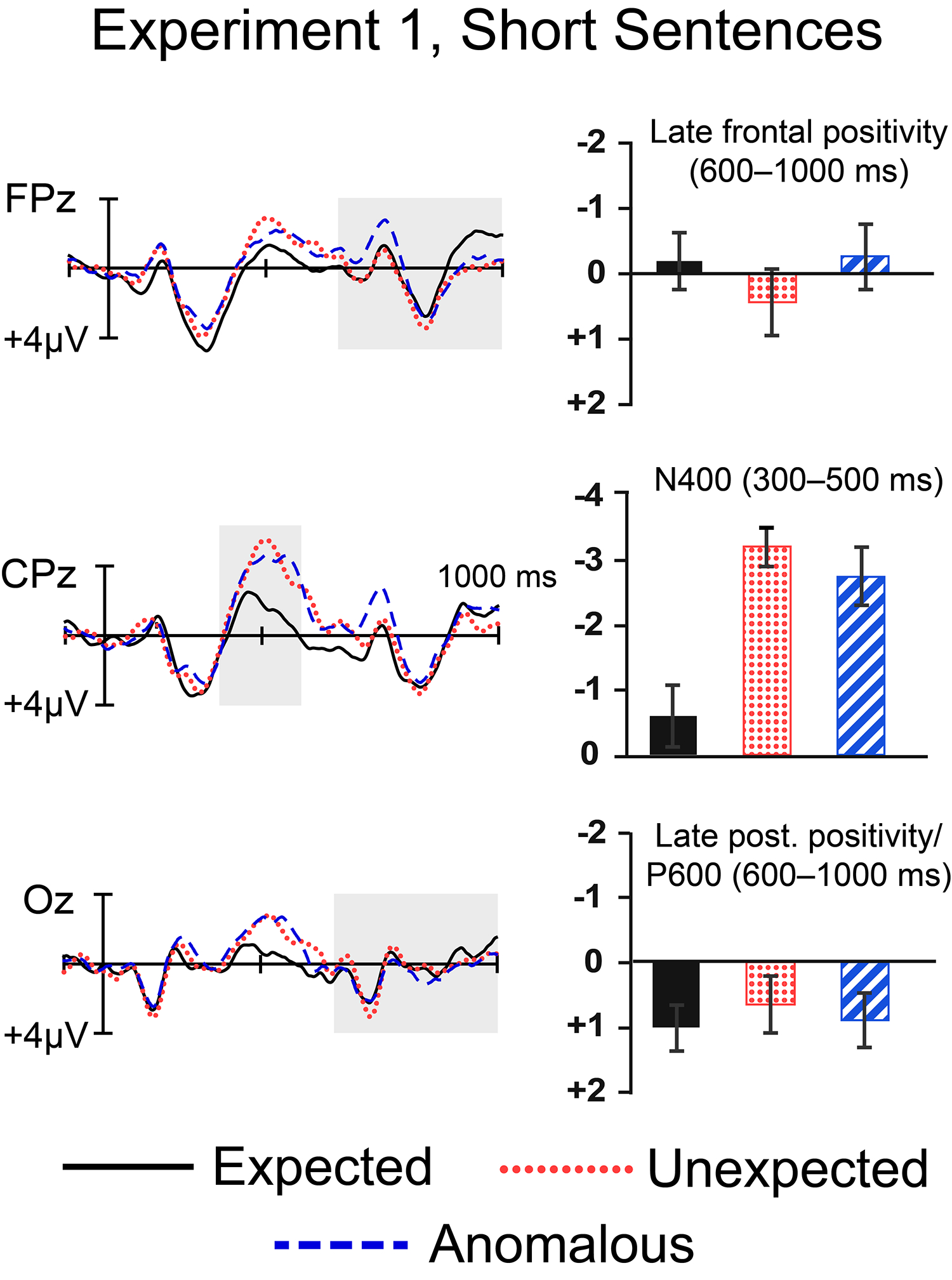
Figure 1.

Grand-average ERPs for the three conditions, plotted at three midline electrode sites. In this and subsequent figures, negative is plotted up, and all waveforms were low-pass filtered at 15Hz for presentation purposes. Bar graphs to the right show average voltages within each spatiotemporal region of interest (see text) with ±1 SEM error bars, calculated within-subjects (Morey, 2008).
