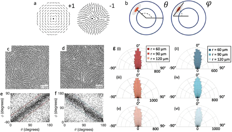
Fig. 1.
Topological defects in fibroblasts. (a) Schematic of a +1 azimuthal and a −1 topological defect. (b) Schematic of θ, corresponding to the angle from the center of the defect, and ϕ, the angle of the major axis of the nucleus. (c) Phase contrast (PC) image of 3T6 cells in the vicinity of a positive defect on r = 120 μm pattern. Scale Bar is 120 μm. (d) PC of 3T6 in the vicinity of a negative defect on r = 120 μm pattern. Scale bar is 120 μm. The ridges are 1.5 μm tall. (e) Scatter plot of 3T6 alignment with r = 90 μm positive defect pattern. Red lines indicate root-mean-square (rms) deviation from the expected angle. The shades of red correspond to the colors specified in (g), indicating the for all the patterns with different ridge spacing. In this case, they overlap. (f) Scatter plot of 3T6 alignment with r =90 μm negative defect pattern. Blue lines indicate rms deviation in angle for all three patterns, corresponding to the shades in (g). Alignment of 3T6 with ridges for (i and ii) r = 60 μm, (iii and iv) r = 90 μm, and (v and vi) r = 120 μm patterns around (i, iii and v) positive defects and (ii, iv and vi) negative defects. Radial axis represents number of cells, and angle represents the deviation of cell alignment from the expected value. (i) has n = 5 samples, and . (ii) has n = 5, and . (iii) has n = 7, and . (iv) has n = 5, and . (v) has n = 5, and . (vi) has n = 5, and .

