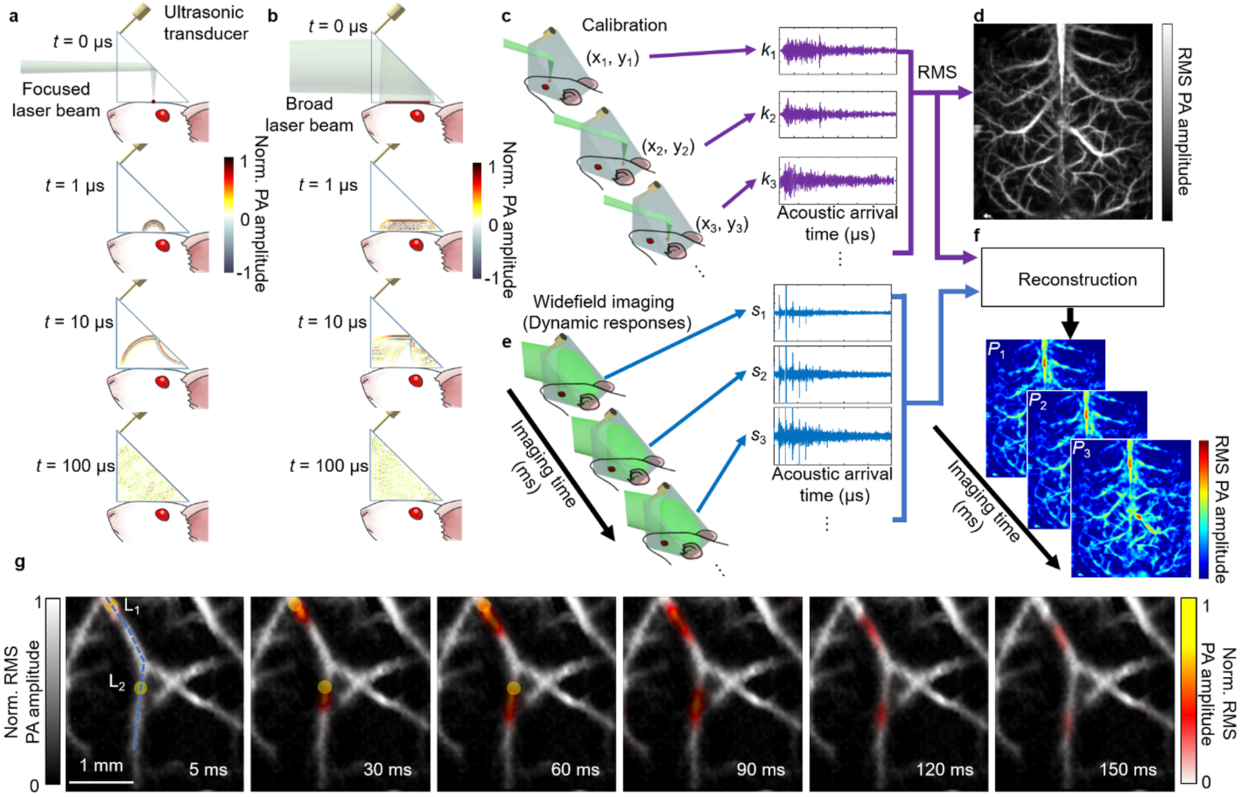
Figure 9.

Principles of PATER and representative images.101 (a–f) Principles of PATER. (a) Simulation of acoustic propagation in the ER in calibration mode. Norm., normalized. (b) Simulation of acoustic propagation in the ER in wide-field mode. (c) In calibration mode, light is focused on each pixel to acquire the impulse response encoded by the ER, ki, and then raster scanned over the FOV. (d) Calibration image formed by computing the root-mean-squared amplitude of each received PA signal at every calibration position. (e) Snapshot wide-field imaging. A broad laser beam illuminates the entire FOV to acquire encoded signals, si, which can be repeated for high-speed imaging. (f) Reconstructed wide-field images. The reconstruction algorithm uses calibrated impulse responses to decode the wide-field signals and then display wide-field images. (g) Monitoring of blood pulse wave propagation. Wide-field images at different time points illustrate the thermal wave propagation in the middle cerebral arteries. The yellow circles, labeled L1, L2, indicate the locations of the laser heating spots during wide-field measurement. The thermal wave signals are shown in color, and the background vessels are shown in gray.
