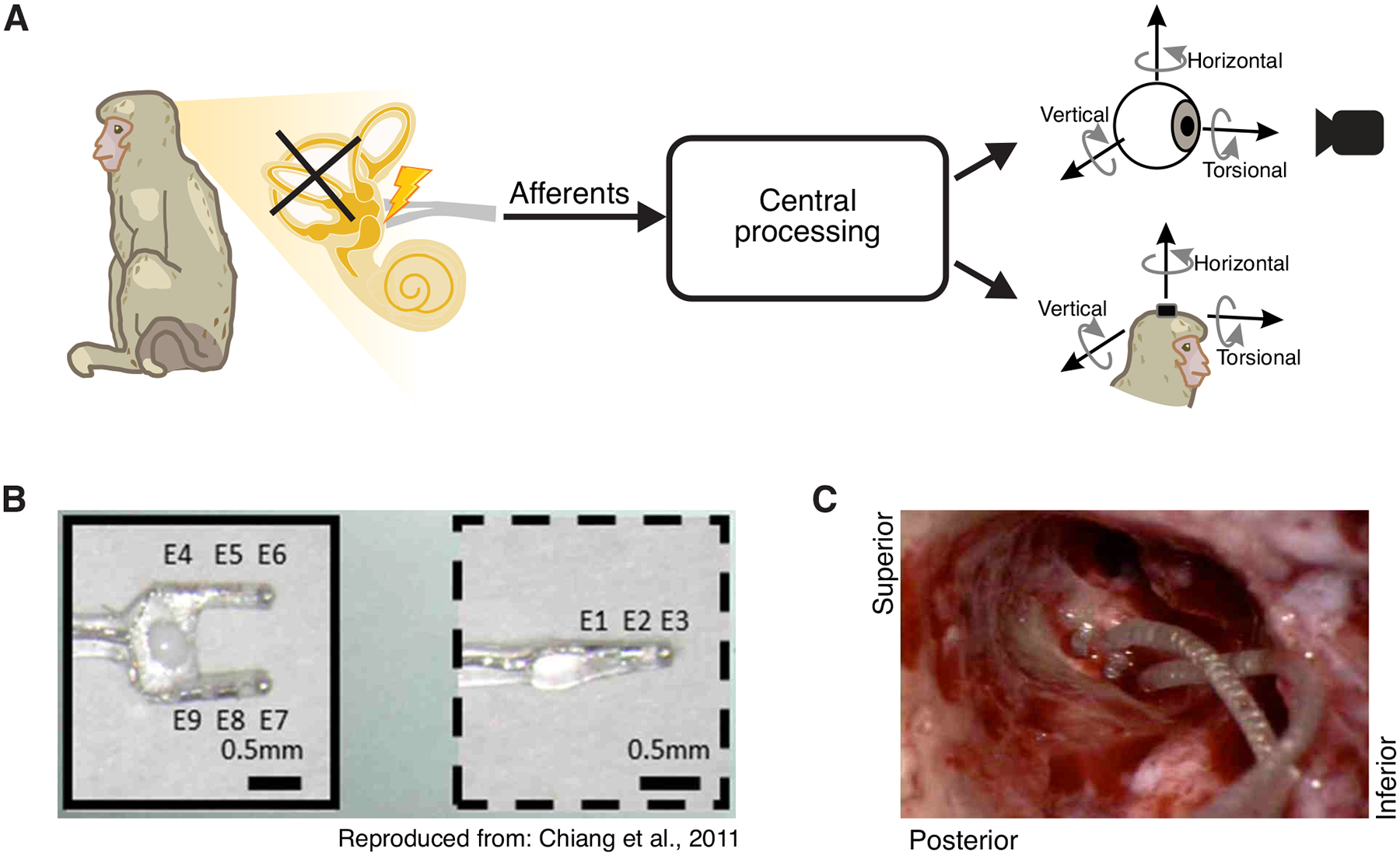
Fig1:

Implantation of vestibular prosthesis stimulating electrodes after prior labyrinthectomy. A) Diagram of the vestibular pathways and the behavioral outputs. Top: 3D videooculography of the evoked eye movement (mediated via the vestibulo-ocular reflex). Bottom: 3D gyroscope measurement of the evoked head movement (mediated via the vestibulo-collic reflex). B) Electrode array image. Reproduced from Chiang et al., 2011. C) Photo of the inner ear during electrode implant surgery. The two-pronged array is on the left while the single-pronged array is on the right.
