Fig4:

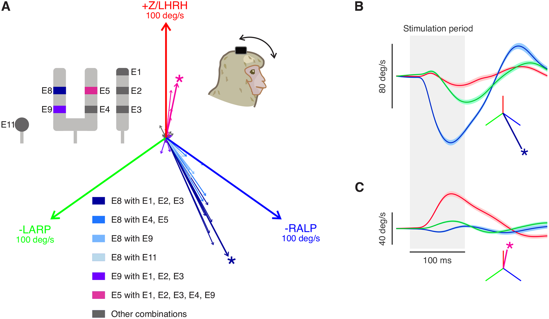
Prosthetic stimulation of vestibular nerves can evoke robust head movements despite prior labyrinthectomy. A) Similar to Fig. 2 but shows vector portrayal of the evoked head movements using all the possible combinations of electrode sites. Again, two main evoked directions were found, aligned with the implanted ear’s anterior canal (blue) and horizontal canal (magenta) axes. The magnitude of each canal axis shown is 100 deg/s. The asterisk denotes the best electrode pair for stimulation in each direction. Inset: diagram of the electrode contacts. E8 paired with all other electrodes is shown in blue. E9 paired with E1–3 is in purple. E5 paired with all other electrodes (except E8) is in magenta B) Example head velocity traces of the evoked VOR in the direction aligned with the anterior canal. Shaded area indicated the SEM. The inset shows the vector representation of the response. C) Example eye velocity traces of the evoked VOR in another direction (aligned with the horizontal canal). Blue, green, and red signify the directions of the -RALP, -LARP, and Z/LHRH, respectively.
