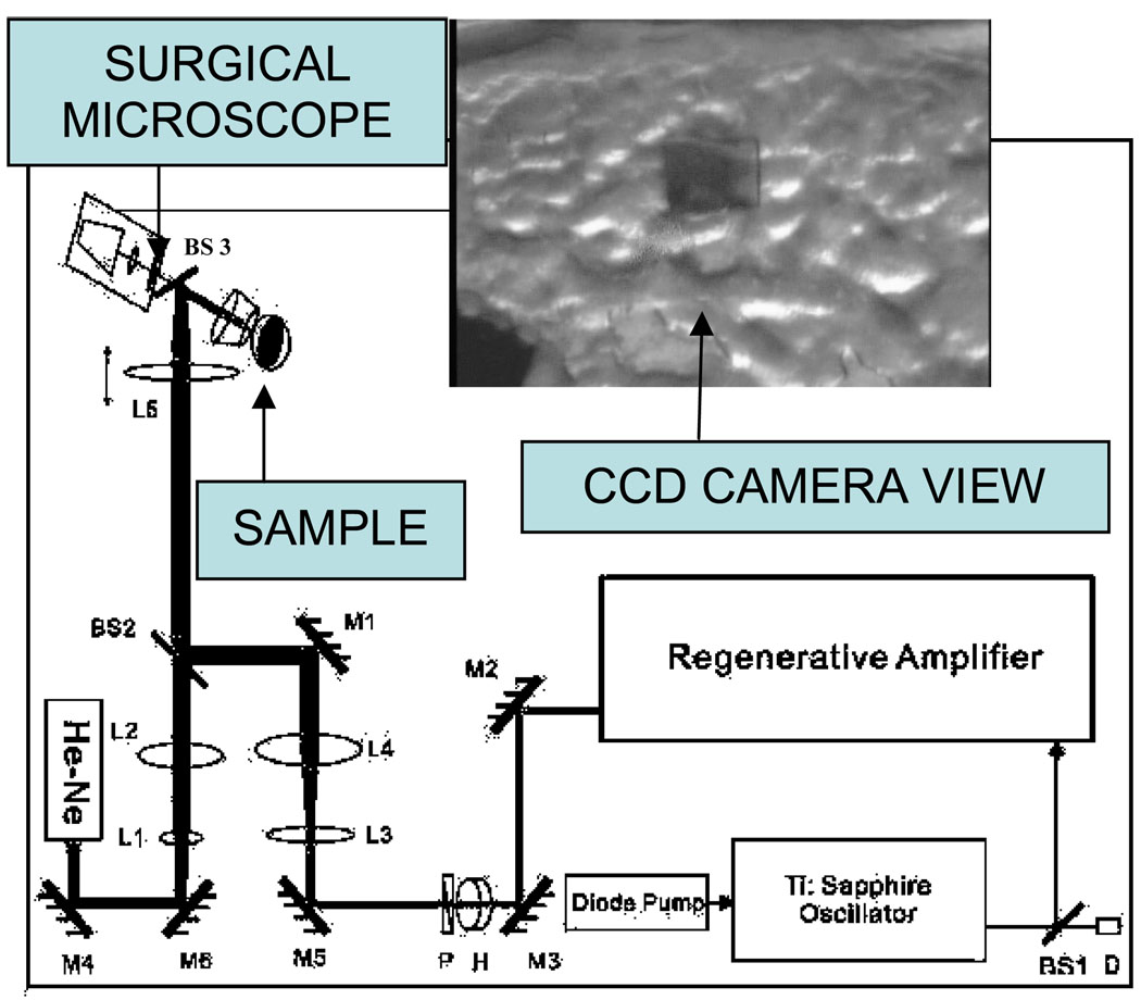
Figure 1.
The optical delivery system. M, mirror; BS, beam splitter; L, lens; D, detector; H, half wave plate; P, polarizer; He-Ne, Helium-Neon laser; paths of the guiding and the Ti-Sapphire beams are shown by the sketch. The inset displays the image of a laser ablated area on the surface of the biofilm taken by the CCD camera.

