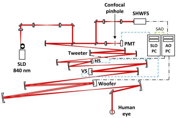
Fig. 1.

Schematic diagram of the AOSLO [25] that consists of a Shack-Hartmann wavefront sensor (SHWFS), a 52-actuator woofer mirror (Mirao 52-e, Imagine Eyes, Inc., France), and a 140-actuator tweeter mirror (Multi-DM MEMS mirror, Boston Micromachines Inc., Cambridge, MA), all in pupil conjugate planes. 840 nm light (superluminescent diode (SLD); Superlum, Ireland) enters the eye’s pupil through a maximum diameter of 8 mm and is scanned (vertical scanner, VS; horizontal scanner, HS) over a 1.5 × 1.5 deg patch of retina. The reflected light is descanned as it propagates back through the system and ~20% is diverted to the SHWFS while the remaining light is focused through a 75 micron confocal pinhole (1.4′, ~1.6 X the width of the Airy disk with an 8 mm pupil) to a photomultiplier tube (PMT) for retinal imaging. One PC performs wavefront sensing and mirror control (AO PC), a second PC acquires and records retinal image sequences (SLO PC). The PCs operate independently during wavefront sensor based control but must communicate during sensorless control (SAO). An open loop correction of lower order aberrations (primarily defocus) is placed on the woofer mirror with the SHWFS prior to initiating closed loop correction with both control methods.
