
Figure 3.
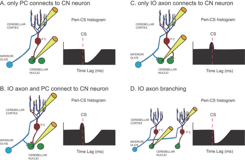
Schematic representation of basic connectivity patterns between IO axon, PC, and CN neuron. (A-C) The three possible ways to connect an IO axon, a recorded PC, and recorded CN neuron are shown along with schematic CS-CN correlograms that each would be expected to produce. (D) An alternative connection pattern due to the branching of IO axons to multiple PCs that would produce a similar CS-CN histogram as that shown in A. Yellow electrodes indicate which cells are being recorded.