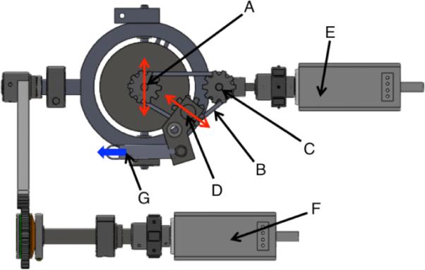
Fig. 4.

View from underneath the device showing the design scheme for maintaining proper tension on the optical axis rotation sprocket/pulley system: (A) optical axis rotation sprocket with the red arrow indicating the lateral movement induced by rotation from the lateral rotation motor, (B) pulley, (C) pulley drive from the optical axis rotation motor, and (D) tension sprocket. The arrows here indicate lateral movements that occur with lateral movement of (A). This is to keep constant tension on the belt. Tension is applied with the spring shown in (G) with the arrow indicating force (F) is the lateral rotation motor.
